Chat

Welcome to Flux

Treat Flux like your intern. Tell it what you'd like to build and it'll get to work. You can also ask it questions, brainstorm ideas, and teach it your preferences. Learn More

Explain project
Write a project description
Find schematic issues
Create a test plan
Simulate a circuit
Prepare for Manufacturing
Component Selection Workflow
New Subsystem Wizard
Write I2C initialization code
Generate firmware skeleton
create a high level mermaid block diagram of this project. Include key component...

@copilot create a high level mermaid block diagram of this project. Include key component's manufacturer part number in each block whenever possible.
1y
Certainly! Below is a high-level mermaid block diagram of your HVAC System controller board project, including the key components with their manufacturer part numbers:

Diagram


I2C / SPI Control Control Power Control WiFi Power Motor Control Power Control ESP32 Module\nESP32-WROOM-32 Environmental Sensor\nBME680 Motor Driver\nL298N Relays\nSRD-05VDC-SL-C Voltage Regulator\nAMS1117-3.3 Interface\nTouchscreen & Buttons WiFi Module\nESP32-WROOM-32 DC Motors "Load (AC Appliances)"
This diagram provides a conceptual overview, illustrating how the ESP32 module interfaces with other components for monitoring, control, and connectivity. Let me know if you'd like further details or adjustments!
1y
3
create a high level mermaid block diagram of this project. Include key component...

@copilot create a high level mermaid block diagram of this project. Include key component's manufacturer part number in each block whenever possible.
1y
Certainly! Here's a high-level Mermaid block diagram that represents the key components of your HVAC system controller board design:
graph TD;
  A[ESP32 Module\n[ESP32-WROOM-32]] -->|I2C| F[Sensor\n[BME680]];
  A -->|GPIO| H[Relays\n[SRD-05VDC-SL-C x4]];
  A -->|GPIO| I[Motor Driver\n[L298N]];
  B[Voltage Regulator\n[AMS1117-3.3]] --> A;
  C[Power Supply\n[5V Input]] --> B;
  C --> I;
  D[Circuit Protection\n[Diodes node_1N4007 x10\n1N4007W x5]] --> F;
  D --> H;
  D --> I;

  subgraph Communication
    A --> J[MQTT Protocol];
    J -->|WiFi| K[Cloud Service];
  end

  subgraph Power Control
    H --> L1[Relay 1];
    H --> L2[Relay 2];
    H --> L3[Relay 3];
    H --> L4[Relay 4];
  end

  subgraph Environmental Monitoring
    F --> M1[Temperature];
    F --> M2[Humidity];
    F --> M3[Pressure];
    F --> M4[Gas Sensor];
  end

  subgraph Motor Control
    I --> N1[DC Motor 1];
    I --> N2[DC Motor 2];
  end
This diagram organizes your project's components into functional blocks, representing their roles and interconnections. Let me know if any modifications are needed!
1y
1

No files yet

Documents

    Documents are markdown text files which describe project goals, capture details, or even simulation outputs.

    Assets

    powerControll.jpg

    powerControll.jpg

    powerControllThumbnail

    hvacController qNac

    hvacController qNac thumbnail
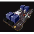
    HVAC System controller board. Features 4 10A250VAC relays (For power control), a BME680 for environmental monitoring and a 5v-35v driver to control up to 2 DC motors. #esp32 #iot

    Properties

    ESP-IDF

    WiFi

    MQTT

    5V

    10 to 90%

    %

    RoHS, FCC, CE

    -10 to 70

    °C

    PCB Trace

    Touchscreen, Buttons

    20,000

    hrs

    10

    yrs

    Small gadget

    1

    4

    Consumer Electronics

    Pricing & Availability

    Distributor

    Qty 1

    Arrow

    $13.87–$18.66

    Digi-Key

    $23.04–$30.53

    LCSC

    $16.63–$19.00

    Mouser

    $23.76

    Verical

    $16.67–$48.06

    Controls