Chat

Welcome to Flux

Treat Flux like your intern. Tell it what you'd like to build and it'll get to work. You can also ask it questions, brainstorm ideas, and teach it your preferences. Learn More

Explain project
Write a project description
Find schematic issues
Create a test plan
Simulate a circuit
Prepare for Manufacturing
Component Selection Workflow
New Subsystem Wizard
sublayout1
create a detailed step by step plan table for this project to verify its functio...

@copilot create a detailed step by step plan table for this project to verify its functionality.
1y
To verify the functionality of your TP4056 Type-C charger project, you can follow a structured plan. Below is a detailed step-by-step plan in tabular form:

Table


StepDescriptionAction Items
1Review Schematic- Ensure the schematic follows design intent.- Validate all connections according to the datasheet and schematic.
2Check Component Values- Confirm resistor, capacitor values (e.g., $R_{prog}$ is 1.2kΩ for 900mA current settings).- Verify the correct part numbers for components.
3PCB Layout Inspection- Check trace widths, clearances.- Ensure proper GND routing and thermal management.
4Load Testing- Connect a load to the BAT connector.- Measure the output current to confirm it is approximately 900mA.
5Thermal Testing- Operate the circuit for an extended period.- Monitor the temperature of the TP4056 and other critical components.
6Voltage Monitoring- Measure voltage at the $V_{BUS}$ and $BAT$ nodes to confirm functionality.- Ensure $V_{BUS}$ voltage levels are correct.
7LED Indicators- Check the operation of CHRG and STDB LEDs.- Confirm indication of charging/standby states.
8USB Connection Test- Connect a USB Type-C power source.- Ensure proper power delivery and detection via the USB interface.
9Continuous Monitoring- Monitor for any issues over extended usage.- Ensure safety limits (overvoltage, overcurrent) are not exceeded.
10Conclusion & Documentation- Summarize findings.- Document any needed corrections or confirmations of proper operation.
Ensure to use appropriate equipment, such as multimeters, oscilloscopes, and thermal cameras, if needed, during testing phases. Let me know if you need further details or adjustments!
1y
2
create a high level mermaid block diagram of this project. Include key component...

@copilot create a high level mermaid block diagram of this project. Include key component's manufacturer part number in each block whenever possible.
1y
Here's a high-level Mermaid block diagram for your TP4056 Type-C charger project. This diagram includes key components and their respective manufacturer part numbers where available:

Diagram


"Input Power Source\n(VIN)" "USB Type-C Connector\n(TYPE-C-31-M-12)" "Charger IC\n(TP4056)" "Rprog\n(1.2kΩ)" "Charging Indicator LED\n(1kΩ)" "Standby Indicator LED\n(1kΩ)" "Capacitor\n(10µF)" "Capacitor\n(0.1µF)" "Capacitor\n(10µF)" "+ BAT -\n(B2B-PH-K-S(LF)(SN))"
This diagram represents the key components and their connections in your charger design. Let me know if there's anything else you'd like to add or modify!
1y
3
Rprog value
Line 1
Rprog = 1.2k; Current = 900mA
J1
CC2
VBAT
CC2
C2
Capacitance
0.1uF
VBAT
VIN
CC1
VIN
C1
Capacitance
10uF
C3
Capacitance
10uF
CC1
VIN
VIN
U1
+ BAT -
R4
Resistance
5.1kΩ
CHRG
R1
Resistance
1kΩ
R2
Resistance
1kΩ
Rprog
Resistance
1.2kΩ
R3
Resistance
5.1kΩ
STDB

No files yet

Documents

    Documents are markdown text files which describe project goals, capture details, or even simulation outputs.

    Assets

    TP4056 Type-C charger-removebg-preview.png

    TP4056 Type-C charger-removebg-preview.png

    TP4056 Type-C charger-removebg-previewThumbnail

    TP4056 Type-C charger

    TP4056 Type-C charger thumbnail
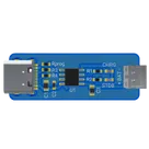
    Tiny USB type-C charger for Li-ion single cell charger based on TP4056 IC. Rprog setting output current to 900mA. VIN and BAT connector are block terminal connectors. #project #typec #charger #TP4056

    Pricing & Availability

    Distributor

    Qty 1

    LCSC

    $0.04–$0.09

    Controls