Chat
Welcome to Flux
Treat Flux like your intern. Tell it what you'd like to build and it'll get to work. You can also ask it questions, brainstorm ideas, and teach it your preferences. Learn More
Explain this part
Write a part description
Describe each pin
Verify Part Details
Recommend similar parts
Check availability & lifecycle

l3akma
copilot
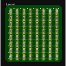
- Anode Rows (labeled AnodeRow1 through AnodeRow8): These are the positive connections of the LEDs, where each row of LEDs shares a common anode connection. The anodes are the longer leads on the LEDs and are typically connected to a positive voltage or switched via a microcontroller to light up the LEDs.
- Kathode Columns (labeled KathodeCol1 through KathodeCol8): These are the negative connections of the LEDs, where each column of LEDs shares a common cathode connection. The cathodes are the shorter leads on the LEDs and are typically grounded or switched via a microcontroller to light up the LEDs.
Wiring:- Each LED in the matrix has its anode connected to one of the 8 anode rows and its cathode connected to one of the 8 cathode columns.
Control Logic:- To light up a specific LED, the corresponding anode row is set high (positive voltage) and the cathode column is set low (ground). This allows current to flow through the selected LED, lighting it up.
- By controlling which rows and columns are activated, you can control the pattern of LEDs that are lit, allowing for the display of characters, symbols, or custom patterns.
Notes:- The project design excludes all kathode and anode connections from the Bill of Materials (BOM) and the PCB, implying they are understood as virtual connections or for simulation purposes within Flux.
- Inputs are prepared for each row and column to facilitate control, possibly by a microcontroller or other control logic hardware not specified in this description.
- The project description includes multiple
Assumptions:Netentries representing connectivity for components, suggesting a structured approach to managing the electrical connections between the kathodes and anodes of the LEDs, although specific details of these connections are abstract and symbolic in this context.