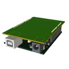
Arduino Uno Pinout Request

give me just the central picture of the pinout, i will add my own wires from there or ask you too but i want the base image with the pinout first
Got it — here are clean base images of the Arduino Uno R3 pinout you can use as your central picture:
Tell me if you prefer SVG or a high‑res PNG, and I’ll fetch the direct file URL and paste it here.
Ask for SVG link
Use high-res pinout PNG
Verify pins match R3
please explain what Arduino Uno R3 PINOUT does.

@copilot please explain what Arduino Uno R3 PINOUT does.
2y
The Arduino Uno R3 PINOUT essentially acts as a reference or guide within your project to help you understand how to connect other components to your Arduino Uno R3. The Arduino Uno R3 is a microcontroller board based on the ATmega328P, and it has a specific layout of pins, including digital and analog inputs/outputs, power supply pins, communication interfaces (like SPI, I2C, and serial), and other functionalities such as interrupt and PWM output capabilities.
Here's a breakdown of what the Arduino Uno R3 PINOUT includes and how it is useful for your shield design:
  • Digital I/O Pins ($0$-$13$): These pins can be used for input and output operations. Pins $0$ and $1$ double as serial communication (TX/RX), and pins $2$ and $3$ support interrupts.
  • Analog Input Pins (A$0$-A$5$): These pins can read analog voltages, making them suitable for sensors and other analog devices.
  • Power Pins (Vin, $3$V$3$, $5$V, GND): These provide various power sources for the board and connected components. Vin is used for an external power source, 3$V3$ is a $3$.3V supply, $5$V is a $5$V supply, and multiple GND pins are for ground connections.
  • Reset Pin: Can be used to reset the microcontroller.
  • Communication Interfaces: This includes SPI, I2C (SDA/SCL on A$4$/A$5$), and serial communication via the RX/TX pins.
For a shield design, referencing the PINOUT is crucial for ensuring compatibility with the Arduino Uno R3. It helps in deciding how to route connections from the shield to the correct pins on the Arduino for power, signal, and interface purposes. The shield can be designed to stack directly on top of the Arduino, utilizing the pinout layout for direct electrical connection and communication between the shield's circuit and the Arduino board.
2y
1
J2
Outline
J3
J4
J1

No files yet

Documents

    Documents are markdown text files which describe project goals, capture details, or even simulation outputs.

    Assets

    Arduino UNO.STEP

    Arduino UNO.STEP

    Arduino UNO 3D3D Model

    Arduino UNO R3 shield - Shape.dxf

    Arduino UNO R3 shield - Shape
    Arduino Uno R3 Shield Template-removebg-preview.png

    Arduino Uno R3 Shield Template-removebg-preview.png

    Arduino Uno R3 Shield Template-removebg-previewThumbnail

    Arduino Uno R3 Shield Template

    Arduino Uno R3 Shield Template thumbnail
    Template for Arduino Uno R3 Shield. Include an official pinout so you will always know Arduino names, the alternative roles of pins, which one is SDA, or SCL, etc. On PCB you can find the 3D model of the Arduino Uno R3 itself along with the board outline on the silkscreen. #Arduino #Uno #Shield #Template #project-template #project

    Properties

    Properties describe core aspects of the project.

    Pricing & Availability

    Distributor

    Qty 1

    Controls