Chat
Welcome to Flux
Treat Flux like your intern. Tell it what you'd like to build and it'll get to work. You can also ask it questions, brainstorm ideas, and teach it your preferences. Learn More
Explain project
Write a project description
Find schematic issues
Create a test plan
Simulate a circuit
Prepare for Manufacturing
Component Selection Workflow
New Subsystem Wizard
Write I2C initialization code
Generate firmware skeleton
please explain what U8 does.

1y
The component designated as U8 in your project is a LAN8710A, which is an Ethernet transceiver used for interfacing network-capable microcontrollers to an Ethernet network. Here's a breakdown of its function:
-
Ethernet Interface: The LAN8710A is a 10/100 Ethernet transceiver. It supports media-independent interface (MII) and reduced media-independent interface (RMII), which are industry-standard interfaces for Ethernet MAC/controllers to connect to Ethernet transceivers.
-
Data Conversion: It handles the conversion of Ethernet signals between the digital signals from the microcontroller or processor and the differential signals required for Ethernet communication on a physical medium like an Ethernet cable.
-
Physical Layer (PHY): The LAN8710A manages the Physical Layer of the Ethernet network, which includes the electrical and signaling elements. It's responsible for the data link layer and provides functionality such as speed and duplex negotiation.
-
Integration with ESP32: Assuming you want to connect the ESP32 module to an Ethernet network, the LAN8710A would be connected to appropriate GPIOs on the ESP32 that manage Ethernet communication.
In your schematic, U8 would be connected to the ESP32 to provide Ethernet functionality to your device. If you need to implement Ethernet connectivity, this component is crucial for handling the network communications.
1y
i want to to show GPIO number for each pin
1y
To show the GPIO number for each pin on the LAN8710A Ethernet transceiver (U8), let's align it with typical GPIO pins from a microcontroller (like the ESP32 in your project). Here's how you might connect the LAN8710A to the ESP32:
-
MDC (Management Data Clock) connects to GPIO pin:
- U8: MDC→ESP32: GPIO23
-
MDIO (Management Data Input/Output) connects to GPIO pin:
- U8: MDIO→ESP32: GPIO18
-
TXD0 to TXD3 (Transmit Data 0-3) connects to GPIO pins:
- U8: TXD0→ESP32: GPIO19
- U8: TXD1→ESP32: GPIO22
- U8: TXD2→ESP32: GPIO23
- U8: TXD3→ESP32: GPIO25
-
RXD0 to RXD3 (Receive Data 0-3) connects to GPIO pins:
- U8: RXD0→ESP32: GPIO34
- U8: RXD1→ESP32: GPIO35
- U8: RXD2→ESP32: GPIO32
- U8: RXD3→ESP32: GPIO33
-
TXEN (Transmit Enable) connects to GPIO pin:
- U8: TXEN→ESP32: GPIO21
-
CRS_DV (Carrier Sense / Data Valid) connects to GPIO pin:
- \text{U8: CRS_DV} \rightarrow \text{ESP32: GPIO36}
-
RXER (Receive Error) connects to GPIO pin:
- U8: RXER→ESP32: GPIO39
Please adjust these GPIO numbers to match the actual design constraints of your project, as different GPIOs may serve different functions or may already be in use. Let me know if you need more adjustments or any other interfaces!
1y
3
please explain what USB1 does.
1y
USB1 in this design is a USB Type-C connector used for both power and data communication for the ESP32-WROOM-32E based device. Here's a breakdown of its functions:
-
Power Supply:
- Pins 15 (VBUS) and 16 (VBUS) are connected to provide power. This VBUS line can be used to power the device.
-
Data Communication:
- Pins 2 (DP1) and 12 (DP2) are used for the USB data positive line (D+).
- Pins 3 (DN1) and 13 (DN2) are used for the USB data negative line (D-).
-
CC (Configuration Channel) Pins:
- Pins 1 (CC1) and 11 (CC2) are configuration channels for USB Type-C. They are used to configure the connection by detecting the cable orientation and power role.
-
Ground and Shielding:
- Pins 7 and 8 are connected to GND, providing a common ground.
- Pins 5, 6, 9, and 10 are connected to SHIELD for reducing electromagnetic interference (EMI) and providing shielding.
-
SBU (Sideband Use) Pins:
- Pins 4 (SBU1) and 14 (SBU2) are sideband use lines, which are typically used in alternate modes like video transmission.
This connector allows for the device to be powered through the USB port and also provides a means for data transfer between the ESP32 and an external host, such as a computer. If you have specific questions regarding connections or functionality, feel free to ask!
1y
5
No files yet
Reviews
Documents
Documents are markdown text files which describe project goals, capture details, or even simulation outputs.
Assets

ESP32-WROOM-32E Reference Design-removebg-preview.png
ESP32-WROOM-32E Reference Design-removebg-previewThumbnailESP32-WROOM-32E Reference Design 3iHk
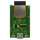
This project is a reference design for an ESP32-WROOM-32E based device. It features USB-C for power and data transfer, onboard voltage regulation, and multiple peripheral connections. It also includes a CH340C for USB to serial conversion #referenceDesign #project #ESP32 #ESP32WROOM #RF #WIFI #MCU #referenceDesign #simple-embedded #espressif #template #reference-design
Properties
Pricing & Availability
Distributor | Qty 1 |
|---|
Controls
Welcome 👋
Flux helps you build PCBs faster with an AI teammate!
Create your account to collaborate, stay updated, fork your own version, and get instant answers from our AI agent.
rasim
copilot
-
USB to Serial Conversion:
- It converts USB data signals into traditional RS-232/serial UART data signals.
- This allows a USB interface to communicate via serial protocols which are commonly used with microcontrollers.
-
Supported Data Rates:
- The CH340C can support various data rates, depending on the configuration, which makes it versatile for different applications.
-
Signal Level Conversion:
- It handles the necessary signal level conversions from USB levels to TTL/CMOS levels used by the microcontroller, making integration straightforward.
Applications: