rafalozano / Power supply +24V to +12V and +3V3

Loaded

0

3

Files

Schematic

PCB

Log InSign Up

Function of Voltage Regulator U1

jskoeppen

jskoeppen

Please explain what @U1 does.
15 days

flux

5:05

Exploring U1 functionality.

Reviewing the bill of materials.

Analyzing the schematic.

Looking for "functional description and what the device does" in en.CD00000444.pdf

Looking for "recommended application circuit and typical use" in en.CD00000444.pdf

Looking for "output voltage, input voltage range, and output current capability" in en.CD00000444.pdf

Looking for "pin functions VIN VOUT GND feedback enable switching node if applicable" in en.CD00000444.pdf

Running multiple web searches.

Found 10 results.

Found 10 results.

Clarifying U1 connections.

U1 is the 12 V regulator in this design.
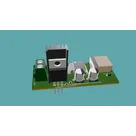
  • In the BOM, U1 is U1, which is a positive fixed linear voltage regulator with a 12 V output and up to about 1.5 A capability in a TO-220 package.
  • In the schematic, its pins are:
    • IN: input supply
    • GND: ground
    • OUT: regulated 12 V output
  • Its OUT pin is on the same net as C3 and C4, which indicates those capacitors are supporting/stabilizing the 12 V rail.
  • Its IN pin is tied to the input side with C6, which suggests C6 is the input bypass/filter capacitor for this regulator.
So, functionally, the path is:
input supply -> U1 -> regulated 12 V output
That fits the project’s stated architecture: a supply that takes 24 V in and generates 12 V and 3.3 V, where U1 is the 12 V branch. The recommended way to explain a project block like this is to describe what is actually connected and use concrete values, which is exactly what this interpretation follows
If you want, I can also explain what U2 does and how it relates to U1.
Explain U2 too
Check U1 support parts
Find U1 datasheet limits
15 days

​
Sign up to send

To get started, talk to Flux or create a New Document.

Reviews

Documents

    Documents are markdown text files which describe project goals, capture details, or even simulation outputs.

    Assets

    Diseño sin título (1).png

    Diseño sin título (1).png

    Diseño sin título (1)Thumbnail

    Power supply +24V to +12V and +3V3

    Power supply +24V to +12V and +3V3  thumbnail
    Power Supply VIN 24V and outputs of 12V and 3.3V using LM2576HVS-3.3/NOPB and L7812CV ICs.

    Properties

    SUBLAYOUT

    Pricing & Availability

    Distributor

    Qty 1

    Digi-Key

    $5.78–$10.70

    LCSC

    $2.31–$2.42

    Mouser

    $1.56

    Controls

    Welcome 👋

    Flux accelerates your PCB design with AI.

    Create your account to start using this component and bring your ideas to life.

        Introducing AI Placement!
        AI Placement Demo

        AI-Powered Component Placement

        Let AI place your components intelligently. AI Placement analyzes your schematic and positions components for optimal routing, signal integrity, and board density.

        From Schematic to Layout in Seconds

        Skip the tedious manual placement. AI Placement generates a starting layout you can refine, saving hours of repetitive work on every new design.

        Works With Auto-Layout

        Pair AI Placement with Auto-Layout for a complete AI-driven PCB design flow — from component placement through trace routing, all with one click.

        Try it