Chat

Welcome to Flux

Treat Flux like your intern. Tell it what you'd like to build and it'll get to work. You can also ask it questions, brainstorm ideas, and teach it your preferences. Learn More

Explain project
Write a project description
Find schematic issues
Create a test plan
Simulate a circuit
Prepare for Manufacturing
Component Selection Workflow
New Subsystem Wizard
connect IC1 to D4, L1, R6 and D4 to 12\_5V net

@copilot connect IC1 to D4, L1, R6 and D4 to 12_5V net
2y
Sure, here are the specific connections for your request:
  1. IC1 (MT3608L):
  2. D4 (SS34):
Here is the summary of the connections:
  • Connect IC1:SW to L1:P1.
  • Connect IC1:IN to VBAT:P1.
  • Connect IC1:EN to VBAT:P1.
  • Connect IC1:FB to R6:P1.
  • Connect D4:A to L1:P2.
  • Connect D4:K to 12_5V:P1.
Let me know if you need any further modifications or connections!
2y
1
J3
C1
Capacitance
10uF
R9
Resistance
20kΩ
R8
Resistance
2kΩ
R7
Resistance
15kΩ
R6
Resistance
150kΩ
C4
Capacitance
4u7 F
R1
Resistance
3kΩ
C2
Capacitance
10uF
C3
Capacitance
100nF
R2
Resistance
1k5 Ω
C8
Capacitance
68pF
R4
Resistance
4k7 Ω
C10
Capacitance
22uF
C9
Capacitance
100nF
R3
Resistance
68kΩ
C7
Capacitance
22uF
R5
Resistance
6k8 Ω
C6
Capacitance
100nF
C5
Capacitance
10uF
IC1
U4
L1
Inductance
10uH
SETTING OUTPUT VOLTAGE
Line 1
------------------------------------------------------------
Line 2
The internal reference VREF is typically 0.6V. The output voltage is divided by a resistor divider,R1 and R2 to the FB pin.
Line 3
Vout = Vref x (1 + R6/R9)
Line 4
------------------------- AND ---------------------------
Line 5
Vout = Vref x (1 + R6/(R1+R4))
D1
J1
D4
D5
Color
Red
D2
Color
Green
D3
L2
Inductance
2u2 H
SW1
J4
J2
U1
U3

No files yet

Documents

    Documents are markdown text files which describe project goals, capture details, or even simulation outputs.

    Assets

    power_manager_board-removebg-preview.png

    power_manager_board-removebg-preview.png

    power_manager_board-removebg-previewThumbnail

    qrcode.svg

    qrcode

    flux logo.svg

    flux logoDefault

    qrcodev2.svg

    qrcodev2
    power manager board.png

    power manager board.png

    power manager board

    Connection Playground: BRAVE POWER MANAGEMENT BOARD

    Connection Playground: BRAVE POWER MANAGEMENT BOARD thumbnail
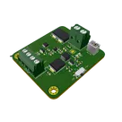
    Brave is a versatile and efficient power board that can provide 12v, 5v and 3.3v outputs for various applications from 4V to 5V Input. It can be powered by battery or solar panel, and the battery can be recharged by solar energy. It can also be powered by a USB port if needed. This board is ideal for IoT projects that require reliable and stable power supply in different environments.
    USB INPUT: 5V Solar INPUT: 4V - 6V Battery Input: 3.6V - 4.2V
    OUTPUTs: 12V, 5V, and 3.3V #IoT #power #management #usb

    Properties

    6

    V

    Pricing & Availability

    Distributor

    Qty 1

    Arrow

    $0.87–$2.30

    Digi-Key

    $0.69–$2.78

    LCSC

    $1.37–$3.10

    Mouser

    $2.66–$3.29

    Verical

    $0.48–$1.85

    Controls