Chat
Welcome to Flux
Treat Flux like your intern. Tell it what you'd like to build and it'll get to work. You can also ask it questions, brainstorm ideas, and teach it your preferences. Learn More
Explain project
Write a project description
Find schematic issues
Create a test plan
Simulate a circuit
Prepare for Manufacturing
Component Selection Workflow
New Subsystem Wizard
Write I2C initialization code
Generate firmware skeleton
New Comment
2
what's is missing in this project that you mention to I do ?

@copilot what's is missing in this project that you mention to I do ?
1y
Based on the project description, here are a few suggestions to enhance or complete your circuit:
-
Power Supply Considerations:
- Ensure that your power supply meets the voltage and current requirements of all components. The ESP32, for example, typically requires 3.3V. You should ensure that Net 1 can supply enough power to all connected components.
-
USB-C Connector:
- Ensure that the USB-C connector is correctly wired for both power and data. Pay attention to the orientation and connections for features like USB OTG, if needed.
-
Voltage Regulation:
- If you haven't already, add a voltage regulator to ensure a stable 3.3V supply, especially if your input is a higher voltage.
-
Decoupling Capacitors:
- Add decoupling capacitors near the power pins of the ESP32 and other ICs like the CH340C to stabilize the power supply.
-
Programming Interface:
- Include any additional pins or interfaces needed to program the ESP32, such as pull-up resistors on the EN and IO0 pins for boot mode selection.
-
Error Handling:
- Add any necessary error indications, such as additional LEDs or a buzzer, to alert for failures or completion of tasks.
-
Schematic and PCB Review:
- Perform a thorough review of the schematic and PCB layout to ensure no unintentional shorts or open nets.
-
I/O Connections:
- Validate if the currently tied IO pins of the ESP32 are appropriate for the sensors and actuators. For instance, ensure that the DHT11 sensor connections are correctly configured.
-
Component Labels:
- Make sure all components are properly labeled and documented in the schematic for easier debugging and understanding.
-
Testing Points:
- Add test points for important signals, such as power lines or communication lines, to facilitate debugging and testing.
Review these aspects and let me know if you need detailed guidance on implementing any specific part!
1y
5
Connect Relay:VCC to ESP32:5V.
Connect Relay:GND to ESP32:GND.
Connect Relay:IN ...
@copilot Connect Relay:VCC to ESP32:5V.
Connect Relay:GND to ESP32:GND.
Connect Relay:IN to ESP32:GPIO5 (or any available GPIO pin).
Connect the lamp through the relay's normally-open (NO) contacts.
1y
Let's translate those instructions into specific connections for your project:
-
Connect Relay Power:
- Connect K1:VCC to a 5V source on your board.
- Connect K1:GND to U1:GND.
-
Connect Relay Control:
- Connect K1:Signal to U1:IO5. Assuming "GPIO5" refers to IO5 on the ESP32.
-
Connect Relay to Load:
- Connect your lamp's positive terminal to K1:COM.
- Connect K1:NO to the positive terminal of the power supply for the lamp.
Ensure that the relay you are using can handle the power requirements of your lamp, and be cautious when dealing with high voltages. Let me know if you need further adjustments or clarifications!
1y
2
U2
LED2
K1
R1
U1
US1
No files yet
Reviews
Documents
Documents are markdown text files which describe project goals, capture details, or even simulation outputs.
Assets

ESP32-WROOM-32E Reference Design-removebg-preview.png
ESP32-WROOM-32E Reference Design-removebg-previewThumbnailESP32-WROOM-32E Reference Design
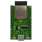
This project is a reference design for an ESP32-WROOM-32E based device. It features USB-C for power and data transfer, onboard voltage regulation, and multiple peripheral connections. It also includes a CH340C for USB to serial conversion #referenceDesign #project #ESP32 #ESP32WROOM #RF #WIFI #MCU #referenceDesign #simple-embedded #espressif #template #reference-design
Properties
Pricing & Availability
Distributor | Qty 1 |
|---|---|
Digi-Key | $0.04 |
LCSC | $1.24 |
Mouser | $6.55 |
Controls
Welcome 👋
Flux helps you build PCBs faster with an AI teammate!
Create your account to collaborate, stay updated, fork your own version, and get instant answers from our AI agent.
pedroberiotto
copilot