Powering Raspberry Pi with MOSFETs
Thought for 1 min 19 sec
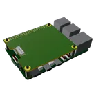
You want a 12 V input stage, 24 switch channels, and 24 two-pin output connectors added to this HAT template.
- I created a plan to preserve the template, add power input/regulation, add the 24 output channels, place the 24 connectors, and verify fit/integration.
- The plan is ready to execute.
Click Start on the plan bar to begin. Let me know if you want any requirement changed first.

so what will happen is the entire system is grounded on the 12v ground, then a power reduction not the pi 5v. then each mossfet wil be n one of the GPIO pins of the 24 available to use, and then the other side of the mossfet goes to each JST connector and then the other side of the JST loops back to the 12v positive. this is a switching station that uses 24 switches to contour a 12v pump on each JST
Thought for 58 sec
You want this template turned into a 24-channel 12 V pump-switching HAT with a shared 12 V supply, onboard 12 V to 5 V conversion, 24 GPIO-controlled low-side switch channels, and 24 two-pin pump outputs.
- The plan is updated and ready to execute.
- It covers power input/conversion, 24 switch channels, 24 output connectors, and full integration.
Click Start on the plan bar to begin.
Add flyback diodes
Use screw terminal input
Choose MOSFET gate parts