Treat Flux like your intern. Tell it what you'd like to build and it'll get to work. You can also ask it questions, brainstorm ideas, and teach it your preferences. Learn More
Creating a schematic for "Smart Open Z Meters" suggests we are working on a project that involves measuring impedance in a smart, possibly networked, manner. Since we don't have specific details about the hardware requirements or the level of precision needed, I'll make assumptions based on common practices for such devices. This design will incorporate the STM32F031F6P6 microcontroller for processing and communication, along with essential components for impedance measurement. Keep in mind this is a starting point, and specific details might need adjustments depending on the exact requirements of your project.
Basic Components:
STM32F031F6P6 Microcontroller (U1): Handles data processing and communication.
Precision Resistance (Rmeasure): Known reference resistance for measuring unknown impedance.
Operational Amplifier (U2): Used in a configuration for impedance measurement.
ADC Input: Utilize the microcontroller's ADC to read the voltage, which is related to the unknown impedance.
Connectivity Overview:
Impedance Measurement Circuit:
Utilize the PA0/ADC&Digital pin of the STM32 (U1:PA0) to measure the voltage across the unknown impedance.
Connect the operational amplifier output to U1:PA0, ensuring it falls within the ADC’s input voltage range.
Reference Resistance (Rmeasure):
Place Rmeasure between the operational amplifier and the point of measurement.
Operational Amplifier (U2):
A generic op-amp can be used here, connected in a configuration that allows impedance measurement (for example, a transimpedance amplifier configuration).
Connect U2's output to Rmeasure and then to the measurement point, with the other side of the measurement point connecting back to U2's inverting input.
Signal Source for Impedance Measurement:
Use another GPIO pin (let's say U1:PA1) to provide a known signal for impedance measurement (U1:PA1 could be connected to the non-inverting input of U2 through a resistor if necessary).
Communication Interface:
Implement UART or I2C for external communication. Let's use USART1 for this example.
Connect USART1_TX (U1:PA9) to your communication module's RX line.
Connect USART1_RX (U1:PA10) to your communication module's TX line.
Specific Connections:
Power Supplies: Connect 3V3 pins and GND appropriately across the microcontroller and other components.
Decoupling Capacitors (C1, C4): Place close to the microcontroller's power pins (U1:VDD and U1:VSS).
RESET Circuit: Connect R1 between U1:NRST and 3V3, and a pushbutton to GND to enable manual reset.
Example Connections:
Connect U1:PA0 to U2:OUTPUT.
Connect U1:PA1 to R2:1, R2:2 to U2:NON-INVERTING INPUT.
Connect U1:PA9 to USART1_TX.
Connect U1:PA10 to USART1_RX.
Connect C1:P1, C1:P2, and C4:P1, C4:P2 across U1:VDD and U1:VSS for decoupling.
This overview provides a starting template. It's essential to adapt the design to the specific requirements of your impedance measurement method and the operational ranges you're dealing with. Also, for communication, choose an interface that matches your application’s needs (UART, I2C, SPI, etc.), considering the external devices or networks it will interface with.
To build a schematic for Smart Open Z Meters based on the STM32F031F6P6 MCU, incorporating precise impedance measurement and communication, let's list all the required components. This list assumes a straightforward approach suitable for various applications but remember, specific components might change based on your exact requirements, like measurement range, precision, and communication protocol.
Microcontroller:
U1: STM32F031F6P6 - Main microcontroller for processing and control.
Impedance Measurement Circuit:
Rmeasure: Precision Reference Resistor - Known value for impedance calculation.
U2: Operational Amplifier (Op-Amp) - For signal conditioning in impedance measurement.
R2: Resistor - For op-amp configuration or biasing, value depends on specific circuit design.
C2, C3: Capacitors - For filtering noise in the measurement circuit, values depend on frequency.
Communication Interface:
Depending on the protocol (assuming UART here):
No additional components required for direct MCU to USB-UART bridge communication.
For more advanced communication (e.g., wireless), specific communication modules (e.g., ESP8266 for WiFi, nRF24 for wireless) and associated antenna/components might be needed.
Power Supply:
C1, C4: Decoupling Capacitors - Typically 0.1 µF for noise suppression on power lines, placed close to the MCU's power pins.
C5: Bulk Capacitor - If the power supply is far, a larger capacitor (e.g., 10 µF) near the MCU might be necessary.
Reset Circuit:
R1: Pull-up Resistor for NRST - Typically 10kΩ, providing a default high state to the reset pin.
SW1: Push Button - For manual reset.
General Purpose Input/Output:
R3: Series Resistor - Optional, for protection on GPIO lines used, value typically 330Ω to 1kΩ.
User Interface (optional):
LEDs, Buttons - For user feedback and input, requiring series resistors (typically 330Ω to 470Ω for LEDs).
Communication Components (Optional, based on requirements):
External USB-UART Bridge - If MCU’s UART is used for debugging or communication with a PC.
Wireless Module (e.g., ESP8266, nRF24) - If wireless communication is needed, along with necessary interface resistors and capacitors.
Sample Bill of Materials (BOM):
STM32F031F6P6 (U1)
Generic Op-Amp (U2)
Precision Resistor (1% tolerance recommended) for Rmeasure
Resistors (R1, R2, R3, series resistors for LEDs/buttons)
Capacitors (C1, C2, C3, C4, C5)
Push Button for manual reset (SW1)
LEDs and additional Buttons (if needed for UI)
Optional: Communication module (ESP8266, nRF24, etc.) and associated components
This list provides a template for starting your Smart Open Z Meters project; however, it's crucial to adjust values and add specific components based on detailed circuit designs and functionality requirements. Each component serves a fundamental purpose in ensuring reliable measurements, effective user interaction, and smooth communication in your smart impedance meter.
2y
1
U1
OP1
No files yet
Reviews
Documents
Documents are markdown text files which describe project goals, capture details, or even simulation outputs.
Assets
STM32F03 template board.png
STM32F03 template boardThumbnail
STM32F03 template board
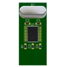
This is example board for creating cool projects with stm32 (this board based on STM32F031F6P6)
#stm32#arm#f0#module
nithin06
copilot
- STM32F031F6P6 Microcontroller (U1): Handles data processing and communication.
- Precision Resistance (Rmeasure): Known reference resistance for measuring unknown impedance.
- Operational Amplifier (U2): Used in a configuration for impedance measurement.
- ADC Input: Utilize the microcontroller's ADC to read the voltage, which is related to the unknown impedance.
Connectivity Overview:-
Impedance Measurement Circuit:
- Utilize the PA0/ADC&Digital pin of the STM32 (U1:PA0) to measure the voltage across the unknown impedance.
- Connect the operational amplifier output to U1:PA0, ensuring it falls within the ADC’s input voltage range.
-
Reference Resistance (Rmeasure):
- Place Rmeasure between the operational amplifier and the point of measurement.
-
Operational Amplifier (U2):
- A generic op-amp can be used here, connected in a configuration that allows impedance measurement (for example, a transimpedance amplifier configuration).
- Connect U2's output to Rmeasure and then to the measurement point, with the other side of the measurement point connecting back to U2's inverting input.
-
Signal Source for Impedance Measurement:
- Use another GPIO pin (let's say U1:PA1) to provide a known signal for impedance measurement (U1:PA1 could be connected to the non-inverting input of U2 through a resistor if necessary).
-
Communication Interface:
- Implement UART or I2C for external communication. Let's use USART1 for this example.
- Connect USART1_TX (U1:PA9) to your communication module's RX line.
- Connect USART1_RX (U1:PA10) to your communication module's TX line.
Specific Connections:- Power Supplies: Connect 3V3 pins and GND appropriately across the microcontroller and other components.
- Decoupling Capacitors (C1, C4): Place close to the microcontroller's power pins (U1:VDD and U1:VSS).
- RESET Circuit: Connect R1 between U1:NRST and 3V3, and a pushbutton to GND to enable manual reset.
Example Connections:Connect U1:PA0 to U2:OUTPUT.Connect U1:PA1 to R2:1, R2:2 to U2:NON-INVERTING INPUT.Connect U1:PA9 to USART1_TX.Connect U1:PA10 to USART1_RX.Connect C1:P1, C1:P2, and C4:P1, C4:P2 across U1:VDD and U1:VSS for decoupling.nithin06
copilot
- U1: STM32F031F6P6 - Main microcontroller for processing and control.
Impedance Measurement Circuit:- Rmeasure: Precision Reference Resistor - Known value for impedance calculation.
- U2: Operational Amplifier (Op-Amp) - For signal conditioning in impedance measurement.
- R2: Resistor - For op-amp configuration or biasing, value depends on specific circuit design.
- C2, C3: Capacitors - For filtering noise in the measurement circuit, values depend on frequency.
Communication Interface:- Depending on the protocol (assuming UART here):
- No additional components required for direct MCU to USB-UART bridge communication.
- For more advanced communication (e.g., wireless), specific communication modules (e.g., ESP8266 for WiFi, nRF24 for wireless) and associated antenna/components might be needed.
Power Supply:- C1, C4: Decoupling Capacitors - Typically 0.1 µF for noise suppression on power lines, placed close to the MCU's power pins.
- C5: Bulk Capacitor - If the power supply is far, a larger capacitor (e.g., 10 µF) near the MCU might be necessary.
Reset Circuit:- R1: Pull-up Resistor for NRST - Typically 10kΩ, providing a default high state to the reset pin.
- SW1: Push Button - For manual reset.
General Purpose Input/Output:- R3: Series Resistor - Optional, for protection on GPIO lines used, value typically 330Ω to 1kΩ.
User Interface (optional):- LEDs, Buttons - For user feedback and input, requiring series resistors (typically 330Ω to 470Ω for LEDs).
Communication Components (Optional, based on requirements):- External USB-UART Bridge - If MCU’s UART is used for debugging or communication with a PC.
- Wireless Module (e.g., ESP8266, nRF24) - If wireless communication is needed, along with necessary interface resistors and capacitors.
Sample Bill of Materials (BOM):