Chat
Welcome to Flux
Treat Flux like your intern. Tell it what you'd like to build and it'll get to work. You can also ask it questions, brainstorm ideas, and teach it your preferences. Learn More
Explain project
Write a project description
Find schematic issues
Create a test plan
Simulate a circuit
Prepare for Manufacturing
Component Selection Workflow
New Subsystem Wizard
Write I2C initialization code
Generate firmware skeleton
is R13 correct as a pull-up resistor?

2y
Based on the information provided, resistor R13 connects to JTAG_TRSTB with a resistance value of 10kΩ. Given its usage in the JTAG interface, it can very well be a pull-up resistor. A pull-up resistor in this case could be providing a default state (usually logic high or '1') when the JTAG line is not actively being driven. However, to verify whether R13 is a pull-up resistor or not, I would also need to know the other pin (P1) connection. If the other pin of R13 is connected to a logic high voltage level or VCC, it would strengthen the argument of R13 being a pull-up resistor.
For confirmation, please provide more details or check the connections as discussed. Making an assumption without additional information could lead to an incorrect interpretation of the circuit.
2y
1
what is a good alternative part for MIMXRT1011
2y
A good alternative would be the ATSAME53J19A-AU microcontroller from Microchip. It is also an Arm Cortex-M7 based microcontroller, running at up to 300 MHz, with better power efficiency. It has 512KB of Flash memory and 192KB of SRAM, a bit more memory than the i.MX RT1010. The ATSAME53 also contains a nice set of peripherals including SPI, USART, I2C, USB, and SDIO, similar to the i.MX RT1010. It can be a drop-in replacement if you're not utilizing the full speed of i.MX RT1010.
Keep in mind that when choosing an alternative part, you need to consider the specifics of your application, and it's important to assess not only the hardware characteristics but also the available software support, including drivers, middleware, and Real-Time Operating Systems (RTOS) support. Also, footprint compatibility is important for hardware design considerations.
However, it's crucial to assess these options carefully as they have different specifications, so one should ensure they meet the requirements of your specific project. As always, please refer to the respective datasheet for a detailed comparison among these options.
2y
4
No files yet
Reviews
Documents
Documents are markdown text files which describe project goals, capture details, or even simulation outputs.
Assets

i.MX RT1010 LoRa Logger-removebg-preview.png
i.MX RT1010 LoRa Logger-removebg-previewThumbnaili.MX RT1010 LoRa Logger
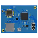
This project is a LoRa data logger implementing the i.MX RT1010 microcontroller. It collects and logs data through the LoRa-E5 module and stores the data via a TF card. Capacitors and resistors are used to construct the necessary circuits, ensuring proper functionality. This system is ideal for long-distance, low-power IoT applications. #project #LoRa #RT1010 #SDCARD
Properties
Bare metal
Lora, JTAG
5V
Buttons, Display
Consumer Electronics
Pricing & Availability
Distributor | Qty 1 |
|---|---|
Digi-Key | $16.90–$17.06 |
LCSC | $10.44–$10.51 |
Mouser | $18.33 |
Controls
Welcome 👋
Flux helps you build PCBs faster with an AI teammate!
Create your account to collaborate, stay updated, fork your own version, and get instant answers from our AI agent.
nico
copilot