Treat Flux like your intern. Tell it what you'd like to build and it'll get to work. You can also ask it questions, brainstorm ideas, and teach it your preferences. Learn More
Connect to your board's 5V line if you're using bus power, otherwise connect it to the main power supply of the MCU. Often, a series protection diode or a polyfuse is added between the USB VBUS and the board's power supply.
Ground (GND):
Connect to the general ground plane of your circuit. The MCU's ground pins are:
Connect U1:VDD to the 5V power supply (using protection if necessary).
Connect U1:VSS, U1:VSSA to the ground of the USB connector.
Remember to use proper ground and power planes in your PCB layout to reduce noise and improve performance. If you need further assistance with component placement or modeling the network, let me know!
To connect the STM32F103C8T6 to a USB Type-C connector, you'll need to connect the appropriate pins for power, ground, and data signals. Here’s a typical setup:
USB Type-C Connector Pins (Example)
VCC (or VBUS): Power supply (typically 5V)
GND: Ground
D+: USB Data Positive
D-: USB Data Negative
STM32F103C8T6 Relevant Pins
VDD (Pins 24, 36, 48): Supply voltage
VSS (Pins 23, 35, 47): Ground
PA11 (Pin 32): USB_D-
PA12 (Pin 33): USB_D+
Connections
Power Supply
Connect STM32F103C8T6:$\text{VDD}$ (24, 36, 48) to USB Type-C Connector:$\text{VCC}$
Connect STM32F103C8T6:$\text{VSS}$ (23, 35, 47) to USB Type-C Connector:$\text{GND}$
USB Data Signals
Connect STM32F103C8T6:$\text{PA11}$ to USB Type-C Connector:$\text{D-}$
Connect STM32F103C8T6:$\text{PA12}$ to USB Type-C Connector:$\text{D+}$
Specific Connections
Connect $\text{U1:VDD}$ to $\text{USB Type-C Connector:VCC}$
Connect $\text{U1:VSS}$ to $\text{USB Type-C Connector:GND}$
Connect $\text{U1:PA11}$ to $\text{USB Type-C Connector:D-}$
Connect $\text{U1:PA12}$ to $\text{USB Type-C Connector:D+}$
This setup assumes you have protection like ESD diodes and possibly a pull-up resistor on the USB lines. If you need further assistance or specifics regarding USB 2.0 protections and considerations, let me know!
2y
2
U1
No files yet
Reviews
Documents
Documents are markdown text files which describe project goals, capture details, or even simulation outputs.
Assets
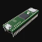
RT1062-Teensy-thumn.png
RT1062-Teensy-thumnThumbnail
RT1062 Teensy 4.1 Template
Template for RT1062 Teensy 4.1 series ARM® Cortex®-M7 MPU Embedded Evaluation Board #template#project-template
Properties
Properties describe core aspects of the project.
Pricing & Availability
Distributor
Qty 1
Arrow
$3.18–$4.00
Digi-Key
$6.11
LCSC
$0.92
Mouser
$5.31
Verical
$3.52–$5.53
Controls
Welcome 👋
Flux helps you build PCBs faster with an AI teammate!
Create your account to collaborate, stay updated, fork your own version, and get instant answers from our AI agent.
naterton
copilot
-
USB D+ (Data Positive):
- U1:PA12
-
USB D- (Data Negative):
- U1:PA11
-
5V Power Supply:
- Connect to your board's 5V line if you're using bus power, otherwise connect it to the main power supply of the MCU. Often, a series protection diode or a polyfuse is added between the USB VBUS and the board's power supply.
-
Ground (GND):
- Connect to the general ground plane of your circuit. The MCU's ground pins are:
- U1:VSS (23, 35, 47)
- U1:VSSA (8)
Example connections: