Chat

Welcome to Flux

Treat Flux like your intern. Tell it what you'd like to build and it'll get to work. You can also ask it questions, brainstorm ideas, and teach it your preferences. Learn More

Explain project
Write a project description
Find schematic issues
Create a test plan
Simulate a circuit
Prepare for Manufacturing
Component Selection Workflow
New Subsystem Wizard
Write I2C initialization code
Generate firmware skeleton
On an array of three batteries, where is located the ground, talking that I want...

@copilot On an array of three batteries, where is located the ground, talking that I want, positive voltage, negative voltage and GND to energize a circuit with Amp Op
1y
When you have an array of three batteries, you can arrange them in series to obtain three different voltage levels that can be used for various parts of a circuit. Here's a way to connect them for your application:
  1. Positive Voltage (+V): Connect the positive terminal of the first battery in the series. This will provide the highest positive voltage level relative to ground.
  2. Ground (GND): Connect the junction between the second and third batteries to serve as the ground reference for your circuit. This point can be considered as 0V.
  3. Negative Voltage (-V): Connect the negative terminal of the third battery. This will provide a negative voltage relative to the ground.
Here's a simple way to visualize the connections:
  • Battery 1 Positive Terminal (+V): Connects to positive load or operational amplifier power supply.
  • Battery 1 Negative Terminal: Connects to Battery 2 Positive Terminal.
  • Battery 2 Negative Terminal (GND): This point is connected to the circuit ground.
  • Battery 3 Positive Terminal: Connects to Battery 2 Negative Terminal.
  • Battery 3 Negative Terminal (-V): Connects to negative load or operational amplifier power supply.
This configuration gives you three voltage levels: positive, ground, and negative, which is helpful for op-amp circuits where dual supplies are often required.
Remember to ensure the batteries are of the same type and capacity to avoid imbalance and potential leakage or over-discharge. Let me know if you need further help with your op-amp circuit design!
1y
1
J2
Outline
J3
J4
J1

No files yet

Documents

    Documents are markdown text files which describe project goals, capture details, or even simulation outputs.

    Assets

    Arduino UNO.STEP

    Arduino UNO.STEP

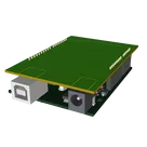
    Arduino UNO 3D3D Model

    Arduino UNO R3 shield - Shape.dxf

    Arduino UNO R3 shield - Shape
    Arduino Uno R3 Shield Template-removebg-preview.png

    Arduino Uno R3 Shield Template-removebg-preview.png

    Arduino Uno R3 Shield Template-removebg-previewThumbnail

    Arduino Uno R3 Shield Template jur5

    Arduino Uno R3 Shield Template jur5 thumbnail
    Template for Arduino Uno R3 Shield. Include an official pinout so you will always know Arduino names, the alternative roles of pins, which one is SDA, or SCL, etc. On PCB you can find the 3D model of the Arduino Uno R3 itself along with the board outline on the silkscreen. #Arduino #Uno #Shield #Template #project-template #project

    Properties

    Properties describe core aspects of the project.

    Pricing & Availability

    Distributor

    Qty 1

    Controls