Circuito PWM con Potenciómetro
0:31
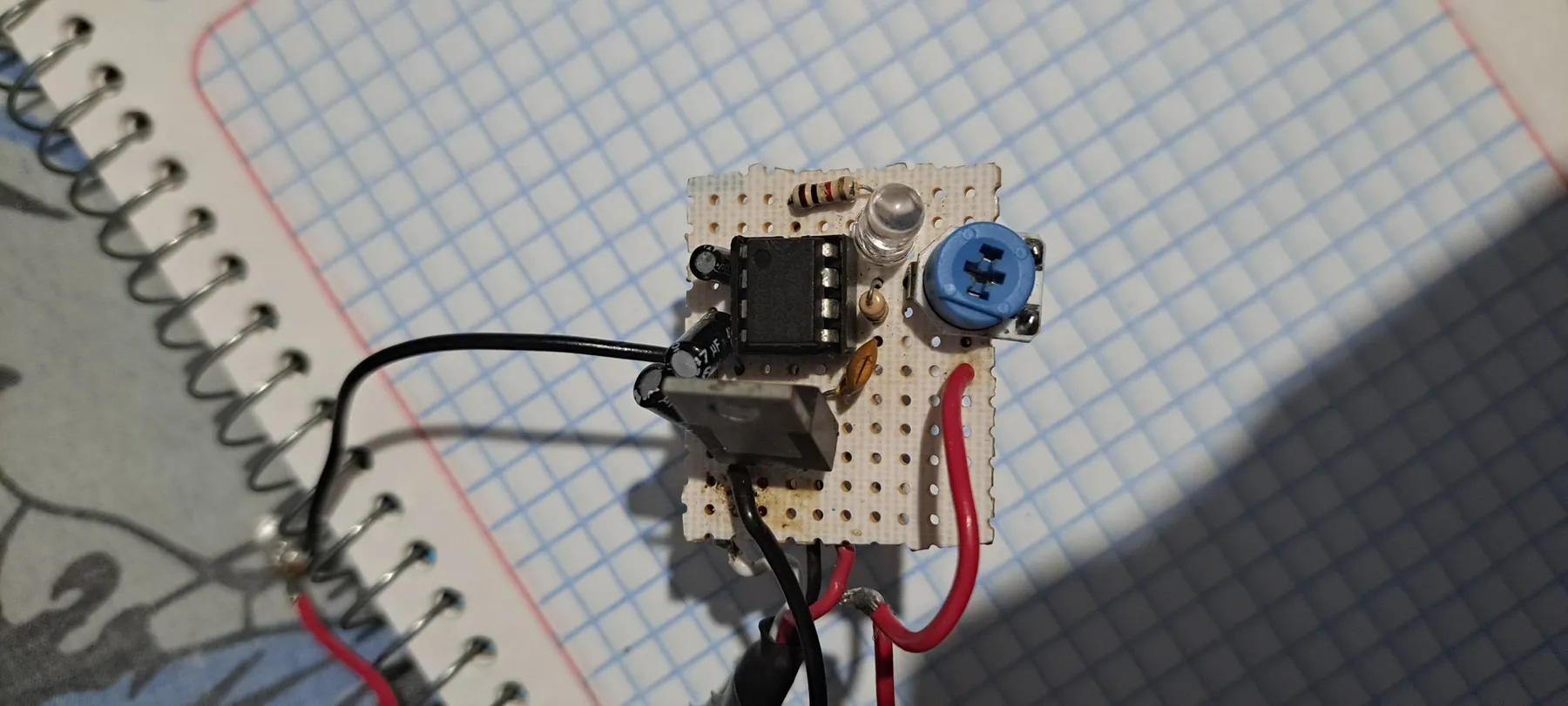
The image shows a small electronics project assembled on a perforated prototyping board. Here’s a breakdown of the identifiable components:
- IC (Integrated Circuit): The central chip appears similar to a 555 timer device, which is common for timing or oscillator applications. (Exact type is not fully determinable from the image alone.)
- Capacitor: An electrolytic capacitor is visible on the bottom left, likely used for filtering or timing functions.
- Resistor: A fixed resistor is positioned near the top, possibly part of a timing network or current-limiting setup.
- Variable Resistor (Potentiometer): The blue, round component on the right appears to be a potentiometer for adjusting resistance values.
- LED: A transparent cylindrical component, positioned near the top center, seems to be an LED that could serve as a status or indicator light.
- Wiring: Red and black wires suggest established power and ground connections.
The overall setup hints at a timing or oscillator circuit, perhaps for blinking an LED or generating pulses.
If you need assistance translating this setup into a schematic within Flux or further details on integrating similar components in your project, let me know how you'd like to proceed!
Component Identification
Circuit Function
Build Schematic
410 days
To get started, talk to Flux or create a New Document.

Welcome 👋
Flux helps you build PCBs faster with an AI teammate!
Create your account to collaborate, stay updated, fork your own version, and get instant answers from our AI agent.