To create a coil-on-plug (COP) control circuit, you generally need a few key components:
Microcontroller or Control Unit: This will control the timing for the ignition coils. Popular choices for custom ignition systems often include Arduino or other microcontrollers.
Ignition Coil Driver: This typically involves a transistor-based circuit to drive the ignition coils, such as an IGBT (Insulated Gate Bipolar Transistor) or a Power MOSFET. It manages the high current and voltage requirements of the ignition coil.
Ignition Coils: If using COP, you'll have multiple ignition coils, one for each spark plug you are controlling.
Timing Sensors: Sensors like a crankshaft position sensor to detect the position of the engine and synchronize the spark timing.
Power Supply: Depending on your ignition coil, you'll need an appropriate power supply, often a 12V or higher DC source.
Here is a basic outline of the circuit:
Control Unit: Connect the control unit to the transistor gates in your driver circuit.
Driver Circuit: Use a transistor (IGBT or MOSFET) connected to the control unit. Transistors switch the ground or power connection to the ignition coils. Connect the transistor's collector (or drain) to the ignition coil and the emitter (or source) to ground. Control the base (or gate) with the microcontroller.
Ignition Coils: Connect one terminal of the coil primary winding to the power supply (VCC) and the other terminal to the collector (or drain) of the transistor.
Sensors: Connect the sensors to the microcontroller to provide the needed timing signals.
Let me know if you need more detailed information or specific components for any part of the circuit!
A coil-on-plug (COP) control circuit is typically used in automotive applications, where each ignition coil is placed directly on top of each spark plug. These circuits require precise control to ensure the timely delivery of high voltage to the spark plugs. Here's a simple approach to designing a basic COP control circuit:
Key Components:
Ignition Coil: Converts low-voltage signals into high-voltage pulses.
Microcontroller or Ignition Module: Controls the timing of when each coil fires.
Switching Device (e.g., NPN transistor or MOSFET): Used for rapidly switching the coil on and off.
Power Supply: 12V automotive battery or another suitable power source.
Diode: Used for flyback protection to prevent back EMF from damaging other components.
Basic Connections:
Power Supply:
Connect the positive terminal of the power supply to the positive side of each ignition coil.
Connect the ground of the power supply to the common ground for all components.
Microcontroller or Ignition Module:
Connect the output control signal from the microcontroller to the base/gate of the switching device.
Switching Device:
Connect the collector/drain of the transistor/MOSFET to the negative terminal of the ignition coil.
Connect the emitter/source of the transistor/MOSFET to ground.
Flyback Diode:
Connect the cathode of the diode to the positive side of the ignition coil.
Connect the anode of the diode to the negative side of the ignition coil.
Example: NPN Transistor Control
Microcontroller Pin → Base of NPN Transistor
Ignition Coil - Negative → Collector of NPN Transistor
Here's a high-level Mermaid block diagram for the project. The diagram highlights the key components and includes the manufacturer part number where possible.
graph TD;
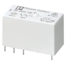
A[Phoenix Contact DPDT Relay<br>Part: MIN RELAY, 2 PDT, 24 VDC] --> COIL_A1[COIL_1<br>Pin: A1];
A --> COIL_A2[COIL_2<br>Pin: A2];
A --> COM_1_PIN[COM_1<br>Pin: 11];
A --> NC_1_PIN[NC_1<br>Pin: 12];
A --> NO_1_PIN[NO_1<br>Pin: 14];
A --> COM_2_PIN[COM_2<br>Pin: 21];
A --> NC_2_PIN[NC_2<br>Pin: 22];
A --> NO_2_PIN[NO_2<br>Pin: 24];
This diagram summarizes the main components and their associated pin numbers as per your project setup. If you need more details or modifications, let me know!
1y
Someone is typing...
3
COM_2
COIL_2
COM_1
COIL_1
NC_2
NO_1
NC_1
NO_2
No files yet
Reviews
Documents
Documents are markdown text files which describe project goals, capture details, or even simulation outputs.
Assets
2961192.kicad_mod
2961192ftpFootprint
2961192_thumb.png
2961192_thumbThumbnail
2961192_3D.stp
2961192_3D3D Model
2961192
2961192 Symbol.svgDefault
DPDT Relay 24VDC
MIN RELAY, 2 PDT, 24 VDC Phoenix Contact SPDT PCB Mount Non-Latching Relay, 24V dc Coil
15.7
Phoenix Contact
jordaz
copilot