中文交流助理

what about the mcu
Great question. Do you want a recommendation for which MCU to use, or guidance on how to hook an MCU up to this power module? A couple quick choices by need:
Integrating an MCU with your module:
  • Power: Feed the MCU’s 3.3 V rail from 3V3. Budget current so total continuous load stays within about 75% of your regulator’s rating.
  • Enable control: EN is pulled up to VIN via R1. If you want the MCU to shut the rail off, have a GPIO (open‑drain or via a small transistor) pull EN low; header J1 Pin_1 breaks EN out.
  • Power‑good: Use U1 PG to hold MCU in reset or as a “rail is OK” input; add a pull‑up on the MCU reset pin if you tie PG into reset.
  • Decoupling: Place a 100 nF ceramic within 5 mm of each MCU VCC/GND pair, and add a nearby bulk ceramic capacitor.
  • I2C, if used: Add 4.7 k pull‑ups to 3V3 and keep total bus capacitance ≤ 400 pF.
Tell me your must‑haves (wireless? GPIO count? sleep current target? package size), and I’ll pick a concrete MCU and map the exact connections to J1, EN, PG, and 3V3.
Clarify MCU requirements
Ask for hookup details
Decoupling clarification
I2C details
Low-power focus
Check out the No Load turn on transient. Test equipment: PSU - Rigol DP832 Scope...

Check out the No Load turn on transient. Test equipment: PSU - Rigol DP832 Scope - Siglent SDS 1202X-E
![img](
Image

Image

https://i.ibb.co/7jTyfC4/IMG-2902.jpg" alt="IMG-2902)
2y
3
https://i.ibb.co/9g4tGRS/Screenshot-2023-10-04-at-3-35-43-PM.png

Image

Image

https://i.ibb.co/9g4tGRS/Screenshot-2023-10-04-at-3-35-43-PM.png
2y
1
3V3
C3
Not Recommended for New Designs
Capacitance
10uF
C1
Not Recommended for New Designs
Capacitance
10uF
PG
C2
Capacitance
1nF
C4
Not Recommended for New Designs
Capacitance
10uF
J1
EN
VIN
VIN
L3
Inductance
1.5uH
EN
R1
Resistance
10kΩ
3V3
H1
U1
Manufacturer Part Number
TPS63051YFFR

No files yet

Documents

    Documents are markdown text files which describe project goals, capture details, or even simulation outputs.

    Assets

    7A083E0094007D99B23FCD9CDCA7F83A.png

    7A083E0094007D99B23FCD9CDCA7F83A.png

    7A083E0094007D99B23FCD9CDCA7F83AThumbnail
    FluxLogoTransparent.svg

    FluxLogoTransparent.svg

    FluxLogoTransparentDefault
    buckboost.png

    buckboost.png

    buckboost
    IMG_2902.jpg

    IMG_2902.jpg

    IMG_2902

    Buck Boost 3.3V 500mA Physical Module

    Buck Boost 3.3V 500mA Physical Module thumbnail
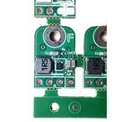
    A buck boost converter that can be powered from a Li-Ion battery and output 3.3V @ 500mA. Powered by the TPS63051YFFR and in the same package as a standard Adafruit buck converter.
    Expect to squeeze around 5-10% SoC from a typical Li-Ion battery.
    Input Voltage Range: 2.5V to 5.5V
    Assembled at pcbway.com

    Pricing & Availability

    Distributor

    Qty 1

    Digi-Key

    $1.40–$1.59

    LCSC

    $0.59

    Mouser

    $3.08

    Controls