Treat Flux like your intern. Tell it what you'd like to build and it'll get to work. You can also ask it questions, brainstorm ideas, and teach it your preferences. Learn More
Place a 0.1µF capacitor (C3) close to each power pin (U1 and U1).
A larger capacitor, such as a 10µF (C4), can also be connected to the power rails for additional filtering.
Reset Circuit:
Connect a 10kΩ resistor (R1) from the NRST pin (U1) to VDD. Note: This connection already exists in your schematic.
Clock Source:
You can use an external crystal or oscillator connected to U1 and U1. In this design, you have an unspecified component X1 with capacitors C1 and C2 connected, which could serve as a crystal oscillator circuit.
Programming Interface:
Connect the SWDIO and SWCLK pins for programming and debugging. These can be connected to the appropriate header or programming connector.
Boot Configuration:
The BOOT0 pin (U1) should be set according to whether you want the microcontroller to boot from memory or a different source. Typically, you might connect it through a pull-down resistor to GND for booting from flash.
Let me know if you need help with connecting other peripherals or interfaces!
1y
1
SPI1_MOSI
SWDIO
I2C1_SDA
USART1_TX
USART1_RX
SPI1_NSS
SPI1_SCK
GND
PA0/ADC&Digital
PB1/ADC
SWCLK
RESET
PA1/ADC&Digital
SPI1_MISO
BOOT0
I2C1_SCL
3V3
C2
Capacitance
22pF
X1
C1
Capacitance
22pF
C4
Capacitance
10uF
U1
C3
Capacitance
0.1uF
U2
R1
Resistance
10kΩ
Resistance
Resistance
No files yet
Reviews
Documents
Documents are markdown text files which describe project goals, capture details, or even simulation outputs.
Assets
STM32F03 template board.png
STM32F03 template boardThumbnail
STM32F03 template board
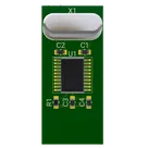
This is example board for creating cool projects with stm32 (this board based on STM32F031F6P6)
#stm32#arm#f0#module
kkonline
copilot