Chat
Hey Leah,
How can I help you?
Note 6
Line 1
This represents the wires that go to the 3PDT switch.
J1
R1
Resistance
47kΩ
J2
Note 1
Line 1
This represents the 9V power supply.
Line 2
P1: 9V
Line 3
P2: GND
J3
D1
Note 5
Line 1
This represents the output jack.
Line 2
P1: Tip
Line 3
P2: Sleeve
Note 2
Line 1
This represents a potentiometer.
SW1
Note 4
Line 1
This represents the input jack.
Line 2
P1: Tip
Line 3
P2: Sleeve
Note 3
Line 1
Put the circuit here.
Line 2
Line 2
Line 3
Line 3
VR1
No files yet
Reviews
Documents
Documents are markdown text files which describe project goals, capture details, or even simulation outputs.
Assets

Subject.png
SubjectThumbnailGuitar Pedal Template
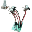
Guitar pedal starter template based on project by Mark Wu. Includes schematic and PCB layout for basic DIY pedal hardware. This includes two 1/4" jacks (one for input and one for output), a 9V power supply (including LED), a 3PDT true bypass wiring setup, and an example potentiometer that can be copy/pasted throughout the circuit.
The headers are meant to be unpopulated so that wires can be soldered to the pads.
PCB design rules imported from the JLCPCB 2-layer stackup template.
Properties
Properties describe core aspects of the project.
Pricing & Availability
Distributor | Qty 1 |
|---|---|
Digi-Key | $0.10 |
LCSC | $0.01 |
Controls
Welcome 👋
Flux helps you build PCBs faster with an AI teammate!
Create your account to collaborate, stay updated, fork your own version, and get instant answers from our AI agent.