Chat
Welcome to Flux
Treat Flux like your intern. Tell it what you'd like to build and it'll get to work. You can also ask it questions, brainstorm ideas, and teach it your preferences. Learn More
Explain project
Write a project description
Find schematic issues
Create a test plan
Simulate a circuit
Prepare for Manufacturing
Component Selection Workflow
New Subsystem Wizard
Add headphone jack

Add headphone jack
1y
2
LeftHeadphone
U2_2IN-
RightInput
U2_2IN+
U2_2IN-
U3_2IN+
LeftInput
RightHeadphone
U2_1IN-
U2_2IN+
U3_1IN-
U3_2IN+
U2_2OUT
LeftInput
U3_1IN-
U3_2OUT
LeftOutput
U3_2OUT
RightOutput
U3_2IN-
U2_1IN+
U2_1OUT
U2_2OUT
LeftOutput
U2_1IN+
RightOutput
U3_2IN-
U3_1OUT
LeftInput
U2_1IN-
U3_1IN+
U3_1IN+
RightInput
U2_1OUT
U3_1OUT
Q3
C12
Capacitance
100nF
C3
Capacitance
1uF
J1
D2
R13
Resistance
10kΩ
R11
Resistance
10 Ω
J2
C13
Capacitance
220uF
R7
Resistance
10 Ω
C8
Capacitance
100nF
J5
C9
Capacitance
100nF
R15
Resistance
22kΩ
J3
C11
Capacitance
220uF
Q2
C1
Capacitance
47uF
R4
Resistance
10kΩ
C10
Capacitance
10uF
C7
Capacitance
100nF
R12
Resistance
10kΩ
R10
Resistance
47 Ω
R2
Resistance
27kΩ
C14
Capacitance
10uF
R17
Resistance
4.7kΩ
R5
Resistance
10kΩ
D3
C5
Capacitance
1uF
C2
Capacitance
1uF
R18
Resistance
47 Ω
R9
Resistance
22kΩ
C4
Capacitance
1uF
R8
Resistance
10 Ω
R6
Resistance
4.7kΩ
R1
Resistance
27kΩ
C6
Capacitance
47uF
R16
Resistance
10 Ω
+18V
D6
Note 8
Line 1
When unplugged, right and left inputs are connected, thereby sending left input through both channels.
Line 2
When plugged in, switch breaks, sending right input through right channel instead of left input.
Line 3
Line 3
Line 4
Line 4
U2
+18V
-9V
+18V
+4.5V
+9V
Note 1
Line 1
DC +9V Power Supply (Center Negative)
Line 2
P1: 9V
Line 3
P2: GND
Q4
-9V
-9V
-9V
+4.5V
Note 5
Line 1
Left Output Jack
Line 2
P1: Tip
Line 3
P2: Sleeve
D4
+18V
+9V
-9V
Q1
J4
D7
U1
+4.5V
D5
R3
Resistance
1MΩ
Note 3
Line 1
Right Input Jack (NC Switched)
Line 2
P1: Tip
Line 3
P2: Sleeve
Line 4
P3: Switch
Note 6
Line 1
Right Output Jack
Line 2
P1: Tip
Line 3
P2: Sleeve
Note 4
Line 1
Left Input Jack
Line 2
P1: Tip
Line 3
P2: Sleeve
Note 9
Line 1
U2 powered at +9V for buffers
Line 2
Line 2
Line 3
Line 3
R14
Resistance
1MΩ
D1
U3
-9V
Note 7
Line 1
Klon Centaur power supply yields +18V to -9V of power
Line 2
Yields +-13.5 of headroom when biased at +4.5V
Line 3
Line 3
Note 10
Line 1
U3 powered at +18V and -9V for amp channels
Line 2
Gives +-13.5 headroom when biased at +4.5V
Line 3
Line 3
No files yet
Reviews
Documents
Documents are markdown text files which describe project goals, capture details, or even simulation outputs.
Assets

Subject.png
SubjectThumbnailPedalboard Headphone Amp
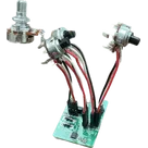
Stereo headphone amp meant to fit in a pedal enclosure for use on a pedalboard. Buffers the signal, then splits it to an output meant to go to a mixer and a headphone out. The headphone amp circuit is applied to the signal before the headphone jack.
Originally designed to give the ability to run effects after an amp simulator pedal with no effects loop. Example chain: amp sim > wet effects > headphone amp > mixer.
References:
 https://electrosmash.com/images/tech/klon-centaur/klon-centaur-power-supply.png
https://aionfx.com/app/files/docs/refractor_documentation.pdf
https://www.muzique.com/lab/buffers.htm
https://electrosmash.com/images/tech/klon-centaur/klon-centaur-power-supply.png
https://aionfx.com/app/files/docs/refractor_documentation.pdf
https://www.muzique.com/lab/buffers.htm
Image
Properties
Properties describe core aspects of the project.
Pricing & Availability
Distributor | Qty 1 |
|---|---|
Arrow | $4.73–$8.86 |
Digi-Key | $9.42–$11.75 |
LCSC | $10.81–$11.27 |
Mouser | $10.58–$11.67 |
Verical | $4.00–$16.35 |
Controls
Welcome 👋
Flux helps you build PCBs faster with an AI teammate!
Create your account to collaborate, stay updated, fork your own version, and get instant answers from our AI agent.
jwwitherspoon