Treat Flux like your intern. Tell it what you'd like to build and it'll get to work. You can also ask it questions, brainstorm ideas, and teach it your preferences. Learn More
To add an I2C LCD screen (20x4) to your Arduino Uno R3 Shield template, you will first need an I2C LCD module, which simplifies the connection to just four wires: VCC, GND, SDA, and SCL. Here’s a basic approach to integrating it into your design:
Assumptions
The I2C LCD 20x4 operates at 5V.
Using a generic I2C LCD 20x4 Display, commonly interfaced with Arduino.
Arduino Uno's standard I2C pins are A4 (SDA) and A5 (SCL).
Steps to Add the I2C LCD Screen 20x4:
Add I2C LCD Component: First, you would need to draw or import the I2C LCD display component if it's not already in your library. Given the lack of a specific component part number (MPN) in your description, we'll treat it as a generic I2C LCD 20x4 module for Arduino.
Wiring the I2C LCD:
Connect the following:
LCD VCC to +5V: Ensures the display has the necessary power.
Connect +5V:P1 to LCD:VCC.
LCD GND to GND: Completes the power circuit.
Connect GND:P1 to LCD:GND.
LCD SDA to Arduino SDA (A4): For data communication.
Assuming a connector pin (let's say J1 Pin 3) corresponds to Arduino Uno R3's A4, connect J1:Pin_3 to LCD:SDA.
LCD SCL to Arduino SCL (A5): For clock signal in data communication.
Assuming a connector pin (let's say J1 Pin 4) corresponds to Arduino Uno R3's A5, connect J1:Pin_4 to LCD:SCL.
Additional Notes
Adjust Component:
Ensure your I2C LCD component has appropriate footprints and pins defined in Flux for the SDA, SCL, VCC, and GND connections.
I2C Address: Most I2C LCD displays have a default address that can be changed with solder jumpers. Make sure the address does not conflict with other I2C devices on the bus.
Software: In your Arduino code, utilize libraries like Wire.h and LiquidCrystal_I2C.h to interface with the display. Initialize the display with its I2C address (commonly $0x27$ or $0x3F$).
This integration should add a functional I2C LCD display to your Arduino Uno R3 Shield project, allowing for rich user interaction with more informative feedback directly from your shield.
2y
1
R1
Resistance
500 Ω
J2
OLED1
SW1
J4
Outline
J3
J1
Arduino Uno R3 PINOUT
No files yet
Reviews
Documents
Documents are markdown text files which describe project goals, capture details, or even simulation outputs.
Assets
Arduino UNO.STEP
Arduino UNO 3D3D Model
Arduino UNO R3 shield - Shape.dxf
Arduino UNO R3 shield - Shape
Arduino Uno R3 Shield Template-removebg-preview.png
Arduino Uno R3 Shield Template-removebg-previewThumbnail
Arduino Uno R3 Shield Template 3yMc
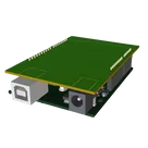
Template for Arduino Uno R3 Shield. Include an official pinout so you will always know Arduino names, the alternative roles of pins, which one is SDA, or SCL, etc. On PCB you can find the 3D model of the Arduino Uno R3 itself along with the board outline on the silkscreen.
#Arduino#Uno#Shield#Template#project-template #project
Properties
Properties describe core aspects of the project.
Pricing & Availability
Distributor
Qty 1
Controls
Welcome 👋
Flux helps you build PCBs faster with an AI teammate!
Create your account to collaborate, stay updated, fork your own version, and get instant answers from our AI agent.
josp11
copilot
- The I2C LCD 20x4 operates at 5V.
- Using a generic I2C LCD 20x4 Display, commonly interfaced with Arduino.
- Arduino Uno's standard I2C pins are A4 (SDA) and A5 (SCL).
Steps to Add the I2C LCD Screen 20x4:-
Add I2C LCD Component: First, you would need to draw or import the I2C LCD display component if it's not already in your library. Given the lack of a specific component part number (MPN) in your description, we'll treat it as a generic I2C LCD 20x4 module for Arduino.
-
Wiring the I2C LCD:
Connect the following:
- LCD VCC to +5V: Ensures the display has the necessary power.
- Connect +5V:P1 to LCD:VCC.
- LCD GND to GND: Completes the power circuit.
- Connect GND:P1 to LCD:GND.
- LCD SDA to Arduino SDA (A4): For data communication.
- Assuming a connector pin (let's say J1 Pin 3) corresponds to Arduino Uno R3's A4, connect J1:Pin_3 to LCD:SDA.
- LCD SCL to Arduino SCL (A5): For clock signal in data communication.
- Assuming a connector pin (let's say J1 Pin 4) corresponds to Arduino Uno R3's A5, connect J1:Pin_4 to LCD:SCL.
Additional NotesWire.handLiquidCrystal_I2C.hto interface with the display. Initialize the display with its I2C address (commonly$0x27$ or$0x3F$).