Here’s what the reviews are telling you right now:
1. Design Rule Checks (DRC)
Only one actual issue:
Project Documentation: Error
“Project has no documentation. Add a project document to capture design decisions, requirements, and specifications.”
This is just a reminder to add a project doc; it doesn’t block design work.
2. Electrical Rule Checks (ERC)
One category with errors:
Missing Power: Error
Power input not connected: U1:VIN (net: —)
Power input not connected: U1:VBAT (net: —)
Your U1 Teensy 4.1 module has its VIN and VBAT pins floating in the schematic. ERC is warning that these power input pins are not tied to any power source.
For now, these ERC/DRC errors do not affect our image-based reverse engineering work; they just mean this project’s own Teensy template schematic is incomplete. When you’re ready to actually wire this reverse‑engineered board into the project, we’ll:
Decide what your board’s input power is (USB, barrel jack, etc.).
Да. Във Flux размерите на платката се коригират от Layout Shape / board setup чрез задаване на форма и точни размери. За правоъгълна платка се задават width и height, а по желание и cornerRadius; може също да се смени stackup-ът едновременно
Най-пряко:
Отвори PCB / Layout изгледа.
Избери Layout.
Промени формата на платката: rectangle, circle или custom.
Въведи точните Width и Height в mm.
Ако е правоъгълна, можеш да зададеш и Corner Radius
Примерна конфигурация според документацията:
rectangle
100 mm × 80 mm
corner radius 2 mm
по желание Standard 4 Layer stackup
Ако искаш, мога да ти кажа и точно как да го направиш в интерфейса стъпка по стъпка, или да ти дам готови размери, ако ми кажеш желаните ширина и височина.
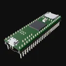
Based on the information available and the MPN (Manufacturer Part Number) being "DEV-16771", it could be inferred that U1 is a Teensy 4.1 development board from PJRC, which integrates an ARM® Cortex®-M7 Microcontroller unit.
If you're in the market for a replacement, you'd likely want another microcontroller-based development board that boasts similar capabilities. Some recommendations include:
Teensy 4.0 (PJRC) - MPN: DEV-15583: A bit of a downgrade from the Teensy 4.1 when it comes to features, this variant uses the same ARM Cortex M7 processor, but lacks the additional IO and SD Card socket.
Arduino Due - MPN: DEV-11589: Sporting an ARM Cortex M3 rather than M7, the Due is comparably well-equipped in terms of I/O pins and functionality. The main sacrifice is the reduced clock speed (84 MHz), which is much less than the 600 MHz boasted by the Teensy 4.1.
STM32F746G-DISCO - MPN: 32F746GDISCOVERY STMicroelectronics: Equipped with a comparable ARM Cortex M7 processor, this board also features a 4.3" 480x272 touchscreen and other high-end features. It may be a little excessive if your project doesn't need all these additional features.
When settling on a replacement, take into account elements such as your project requirements, its price, current availability, and any necessary changes to your schematic to accommodate the new board. Be sure to verify the exact technical specifications and appropriateness from the manufacturer's datasheet or website.
2y
Someone is typing...
2
Check that all reset/enable have an external pull-up or pull-down resistors. Rep...
Based on the information provided for the RT1062 Teensy 4.1 template, the key detail here is ensuring that all reset or enable lines are appropriately biased using external resistors. Given the component provided (U1) and its pins, we need to identify any pins that function as reset or enable lines.
For the Teensy 4.1 (U1) based on the MPN provided and common practices with microcontroller units (MCUs) and similar embedded devices:
The PROGRAM pin (pin 3) often acts as a reset or a programming mode selector for the device. This pin typically requires a pull-up resistor to ensure the device boots normally when not being programmed.
The ON/OFF pin (pin 4), if it functions as an enable pin for the device, it usually requires either a pull-up or pull-down resistor depending on the default state required for the intended operation.
Unfortunately, without the data sheet excerpts specifically detailing the behavior of these pins for the DEV-16771, I'm making assumptions based on common practices with similar devices. Typically, for reset pins, a pull-up resistor in the range of 4.7kΩ to 10kΩ is commonly used, while enable pins might vary more depending on the specific requirements (active high or active low) of the circuit.
Action Items:
Connect a Pull-Up Resistor to the PROGRAM Pin: Assuming it behaves like a typical microcontroller reset pin, connect a 10kΩ resistor from pin 3 (U1:PROGRAM) to a positive power supply rail appropriate for the device's voltage. This ensures that the device does not inadvertently enter programming mode.
Connect R1:1 to U1:PROGRAM
Connect R1:2 to VCC (where VCC matches the operating voltage of the device)
Determine the Required State for the ON/OFF Pin: If it's an enable pin, confirm whether it requires a high or low state for normal operation. If it's active high:
Connect a Pull-Up Resistor to pin 4 (U1:ON/OFF) and to VCC for enabling the device by default.
Connect R2:1 to U1:ON/OFF
Connect R2:2 to VCC
Or, if it's active low:
Connect a Pull-Down Resistor to pin 4 (U1:ON/OFF) and to GND to keep the device disabled by default.
Connect R3:1 to U1:ON/OFF
Connect R3:2 to GND
These steps are based on common MCU/MPU design practices. It is highly recommended to review the specific datasheet for the DEV-16771 part used in the Teensy 4.1 to confirm the correct use and values of these resistors. Without direct excerpts from the datasheet regarding these pins, these recommendations are tentative and should be validated with the actual component datasheet.
It looks like your project is currently an empty template with a single component: the Teensy 4.1 Development Board (DEV-16771). Here are a few points to consider and some questions to better understand your requirements:
Power Connections:
Make sure to connect the power supply correctly.
For example: Connect U1:VIN to your main power source, and connect U1:GND to ground.
Peripheral Connections:
Depending on what peripherals or additional components you want to include, you'll need to connect the respective pins.
Basic Operation:
Ensure you have connections for programming and basic operation.
For example:
Connect U1:PROGRAM to your programming interface.
Connect U1:ON/OFF for controlling power state if necessary.
To help further, I'd need more details on what additional components you plan to use and what your design goals are. Here are some questions that might clarify things:
What power source do you intend to use (e.g., USB, battery)?
Are there any specific peripherals you plan to connect (sensors, actuators, communication modules)?
Do you need any specific interfaces (e.g., SPI, I2C, UART) connected to external devices?
Providing answers to these questions will help in giving more targeted advice.
1y
Someone is typing...
4
create a detailed step by step plan table for U1 to verify its functionality.
Sure, I can create a detailed step-by-step testing plan to verify the functionality of DEV-16771. This plan will be structured to test the basic functionalities including power, communication, and peripheral interfaces. Here's the table:
Table
Step
Description
Connections
Expected Outcome
1
Power Connection
- Connect U1:VIN to a 5V power source - Connect U1:GND to ground
Module should power up, and an initial status indication (such as an LED) may light up
djritmo
copilot