PCB Design for NRF Box

I’ll create a single‑sided, laser‑etch‑friendly PCB with an ESP32 DevKit (30‑pin), NRF24L01 module(s), a 0.96" OLED, and five push buttons, and then generate ready‑to‑fab Gerbers. Steps:
  1. Add ESP32 DevKit 30-pin, NRF24L01 module, 0.96 inch OLED, and five Tactile Push Button.
  2. Wire SPI for NRF(s), I2C/SPI for OLED, and GPIOs for buttons with pull‑ups.
  3. Set single‑layer rules with wide trace/space, add ground pour and jumpers.
  4. Place, route, label, and export Gerbers.
Click Start on the plan bar when ready, or tell me any changes you want.
Use ciphers git hub for exact wiring and components
I will build a single-sided, laser-etch-friendly PCB that exactly follows Cipher’s GitHub wiring and components. Steps:
  1. Pull BOM, pin map, and footprints from the GitHub reference.
  2. Add ESP32 DevKit 30‑pin, 3x NRF24L01 module, 0.96" OLED, and 5x Tactile Push Button; wire exactly per repo.
  3. Configure single-sided rules, add ground pour and 0 Ω jumpers; place and route.
  4. Run DRC and export ready-to-etch Gerbers (etch-around-traces).
Click Start on the plan bar to run it. If you want changes, let me know.
Quick confirms:
  • Share the exact GitHub URL/branch or commit to follow.
  • Confirm it’s 3x NRF24L01 modules on 2×4 2.54 mm headers and the OLED interface (I2C or SPI) per that repo.
  • What trace/space can your laser do (e.g., 12/12 mil) and any board size/outline constraints?
Share GitHub link
Check existing schematic
Find exact parts
U1
which is vcc

@copilot which is vcc
2y
In the context of this OLED display module, the VCC corresponds to the supply voltage. From your project description, it appears that this voltage corresponds to the 5V pin on OLED1. So the 5V designator would be your VCC. Here is how it relates to the other pins:
  • VCC/Supply voltage: OLED1 Pin 3 (5V)
  • Ground: OLED1 Pin 4 (GND)
  • SDA (Serial Data Line for I2C): OLED1 Pin 1 (SDA)
  • SCL (Serial Clock Line for I2C): OLED1 Pin 2 (SCL)
Do you need help in wiring these up on your schematic in Flux?
2y
Cual pin va a tierra?
2y
En el módulo de visualización OLED, el pin que va a tierra (Ground o GND) es el Pin 4 del componente OLED1. En tu proyecto, esto se representa como:
  • Tierra (Ground): OLED1 Pin 4 (GND)
Si necesitas más ayuda con las conexiones o tienes alguna otra pregunta, ¡hazmelo saber!
2y
Someone is typing...
2
please explain what OLED1 does.

@copilot please explain what OLED1 does.
2y
Something went wrong, sorry. Please try again.
2y
Someone is typing...
3
OLED1
U2
GND
SDA
SCL
5V

No files yet

Documents

    Documents are markdown text files which describe project goals, capture details, or even simulation outputs.

    Assets

    ssd1306.svg

    ssd1306.svg

    ssd1306Default
    SSD1306_OLED_Display(128x64).step

    SSD1306_OLED_Display(128x64).step

    3D_SSD1306_OLED_Display(128x64)3D Model

    128x64OLED.kicad_mod

    128x64OLEDFootprint
    ssd1306.png

    ssd1306.png

    ssd1306Thumbnail

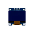
    OLED 128 x 64 0.96inch

    OLED 128 x 64 0.96inch thumbnail
    3.3V I2C Integration: Lolin WeMos D1 mini Pro v4.0 with AHT10 Sensor and 0.96" SSD1306 OLED (No Pull-ups, Shared Bus)

    Properties

    Display Device

    Diagram


    SCL SDA 3.3V GND SCL SDA 3.3V GND SCL SDA 3.3V GND "D1 mini Pro\nI2C Master" "OLED Display" "AHT10 Sensor" "SCL" "SDA" "3.3V Power Rail" "Common Ground"

    OLED

    Pricing & Availability

    Distributor

    Qty 1

    LCSC

    $0.69

    Controls