Chat
Welcome to Flux
Treat Flux like your intern. Tell it what you'd like to build and it'll get to work. You can also ask it questions, brainstorm ideas, and teach it your preferences. Learn More
Explain this part
Write a part description
Describe each pin
Operating conditions
Electrical max ratings
Part Specifications
Application circuits
Verify Part Details
Recommend similar parts
Check availability & lifecycle
Holis


Someone is typing...
9
how do I use Flux?

how i wiring
2y
@copilot how do I use Flux?
2y
To use Flux effectively, here's a basic step-by-step guide:
-
Create an account: Head over to the Flux website and sign up for an account. You'll need this to access both the software and the community features.
-
Open the schematic editor: After you've logged in, you can start a new project by clicking on "New Project". This will open the schematic editor where you can design your electronic circuits.
-
Place components on the schematic: On the left-hand side, you'll see a toolbar with different components. You can drag and drop these onto the schematic.
-
Connect components: Once you've placed your components, you can connect them by drawing wires between their connection points (usually represented by circles or squares).
-
Simulate circuits: Once your schematic is complete, you can simulate your circuit to see how it operates under various conditions.
-
Create PCB layout: After your simulation, you can then create a PCB layout based on the schematic. This allows you to physically arrange your components and routes the connections between them.
-
Export for manufacturing: Once your PCB layout is complete, you can export your design in a format suitable for manufacturing.
-
Ask for help: If you come across any issues, feel free to ask your questions in this comment thread or on the Flux community Slack.
For more in-depth tutorials and to get started on your first project in Flux, you can check out the Flux documentation and the YouTube tutorials provided by Flux[1], [2].
Remember to use the 'Take Action' button if the Copilot suggests specific connections in your schematic and you want it to do those for you[3].
Please let me know if you have any specific questions about any features of Flux, I'm here to help!
2y
Someone is typing...
2
Check that all reset/enable have an external pull-up or pull-down resistors. Rep...

@copilot Check that all reset/enable have an external pull-up or pull-down resistors. Report action items in an ordered list.
2y
The current project description provided does not mention any reset or enable pins in the schematic. Hence, I was not able to check for the inclusion of any external pull-up or pull-down resistors associated with the reset/enable pins.
However, I can provide some general recommendations on adding pull-up or pull-down resistors for the reset or enable pins. These would be some action items you can take:
-
Identify any reset or enable pins in your circuit. If any, they often can be found on components like MCUs, logic gates, or other digital ICs.
-
For each of these pins, add an external pull-up or pull-down resistor as appropriate:
- Enable pins typically requires a pull-up resistor to ensure a default 'HIGH' state when not actively being pulled low.
- Reset pins usually require a pull-down resistor to ensure the system doesn't unexpectedly enter a reset state due to electrical noise.
-
Ensure values of resistors are suitable for your power supply and load currents. Common resistor values for pull-up or pull-down configurations are typically in the range of 4.7k ohms to 10k ohms.
-
Verify that the chosen resistors do not breach any pin input current limitations of the connected devices.
-
Once resistors are added in your Flux project, check the correctness of their connections and polarities.
-
Finally, simulate the design to ensure correct operation of the reset/enable function.
As you refine your schematic with additional components, I would recommend keeping these points in mind.
2y
Someone is typing...
3
@jharwinbarrozo this part is self refferential. Please remove Batt1

@jharwinbarrozo this part is self refferential. Please remove Batt1
1
Someone is typing...
6
No files yet
Reviews
Documents
Documents are markdown text files which describe project goals, capture details, or even simulation outputs.


1070TR
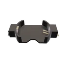
Battery Holder (Open) Coin, 20.0mm 1 Cell SMD (SMT) Tab
bate or batt
#forLedBlink
Properties
Pricing & Availability
Distributor | Qty 1 |
|---|
Controls
Welcome 👋
Flux accelerates your PCB design with AI.
Create your account to start using this component and bring your ideas to life.
pekarthik
1