Powerbank Project Overview
Thought for 5 mins 15 sec
134 days
Gerne. Hier ist eine verständliche Erklärung auf Deutsch, was die aktuelle Schaltung macht und wie die Baugruppen zusammenarbeiten.
Überblick
Diese Platine ist eine Powerbank-Hauptplatine für ein 1-zelliges Li-Ion/Li-Po-Akkusystem.
Die zentrale Steuerung übernimmt U1, ein integrierter Powerbank-/USB-PD-Controller.
Die zentrale Steuerung übernimmt U1, ein integrierter Powerbank-/USB-PD-Controller.
Nach Datenblatt von U1 kann die Schaltung:
- den Akku laden
- aus dem Akku wieder USB-Ausgangsspannung erzeugen
- USB PD2.0 / PD3.0 bidirektional unterstützen
- PPS unterstützen
- feste Profile 5 V, 9 V, 12 V ausgeben
- maximal 18 W liefern
- Schnellladeerkennung über D+/D- und USB-C-CC-Leitungen machen
Wichtig: Diese Schaltung ist nicht 100 W, sondern laut Datenblatt von U1 eine 18-W-Klasse.
Hauptfunktion der Platine
Die Platine hat drei Kernaufgaben:
1. Akku laden
Laut Datenblatt von U1:
- bei Akkuspannung unter 3 V: Trickle-Charge mit 250 mA
- danach Konstantstromladung
- maximaler Batterieladestrom: 5.0 A
- bei normalem 5 V Eingang: max. 10 W Ladeleistung
- bei Schnelllade-Eingang: max. 18 W
- Ladeschaltfrequenz: 500 kHz
Wenn kein Ladebetrieb aktiv ist, kann U1 aus der Akkuspannung wieder geregelte USB-Ausgänge erzeugen.
Laut Datenblatt von U1:
- Ausgangsspannung: 5 V bis 12 V
- Leistungsprofile:
- 5 V / 3.1 A
- 9 V / 2.0 A
- 12 V / 1.5 A
- maximale Ausgangsleistung: 18 W
- Boost-Schaltfrequenz: 375 kHz
Die LEDs D1, D2, D3, D4 dienen als Akkustandsanzeige.
Der Ausgang KEY von U1 zeigt laut Datenblatt den Schnelllademodus an. In der Schaltung hängt daran R5 mit D8.
Welche Ports aktuell vorhanden sind
Der Ausgang KEY von U1 zeigt laut Datenblatt den Schnelllademodus an. In der Schaltung hängt daran R5 mit D8.
Nach der aktuell sichtbaren Schaltung sind diese USB-Ports eingebunden:
Ports der aktuellen Schaltung
Table
Der Port J1 ist als klassischer 5-V-Ladeeingang eingebunden.
Relevante Verbindungen:
Laut Datenblatt:
- VIN ist der Eingangserkennungspin für den Ladepfad
- DMB/DPB werden für Schnelllade-/Porterkennung am Micro-USB-Port verwendet
Das bedeutet:
- Q4 ist ein Eingangsschalter bzw. Schutz-/Power-Path-FET für den VIN-Pfad.
Der Port J2 ist der wichtigste und modernste Anschluss der Schaltung.
Relevante Verbindungen:
Laut Datenblatt:
- CC1/CC2 sind die USB-Type-C-Erkennungspins
- VBUS ist der Ladeversorgungserkennungspin
- DPC/DMC dienen der Schnelllade-/Porterkennung am USB-C-Port
Zusätzlich wird der USB-C-Eingangspfad über Q2 gesteuert:
Das bedeutet:
- Q2 schaltet bzw. schützt den VBUS-Eingang des USB-C-Ports.
Der Port J3 ist ein geregelter Ausgangsport.
Relevante Verbindungen:
Laut Datenblatt:
- DPA1/DMA1 sind die D+/D--Pins für Schnellladeerkennung am Ausgangsport 1
- VOUT1G ist das NMOS-Steuersignal für den Ausgangsport 1
- VOUT1 ist die Last-/Port-Erkennung für Ausgangsport 1
In deiner Schaltung:
Das heißt:
- Q3 ist der Leistungsschalter für USB-A-Ausgang 1.
Der Port J4 ist ähnlich wie der erste Ausgang aufgebaut.
Relevante Verbindungen:
Laut Datenblatt:
- DPA2/DMA2 sind die D+/D--Pins für Schnellladeerkennung am Ausgangsport 2
- VOUT2G ist das NMOS-Steuersignal für Ausgangsport 2
- VOUT2 ist die Last-/Port-Erkennung für Ausgangsport 2
In der Schaltung:
Das heißt:
- Q1 schaltet den zweiten USB-A-Ausgang.
Laut Datenblatt:
- LX ist der Schaltknoten des DC/DC-Wandlers
- BST ist der Bootstrap-Treiberanschluss
- zwischen BST und LX gehört ein Kondensator
In der Schaltung:
Damit bildet:
Ein- und Ausgangskondensatoren
Viele Kondensatoren dienen der Stabilisierung und Filterung:
- Akku/Regler-nah: C1, C2
- VSYS-/Leistungspfad: C3, C4, C5, C15, C16, C17, C18, C19, C20, CP4, CP6, C12
- Ausgangsport 1: C7
- Ausgangsport 2: C9
- Eingänge: C13, CP10
Funktion:
- Stromspitzen puffern
- Ausgangsripple reduzieren
- den Schaltregler stabil halten
- Hot-Plug-Verhalten an USB-Ports verbessern
U1 besitzt laut Datenblatt die Sense-Pins:
- VSP = positive VSYS current sense
- VSN = negative VSYS current sense
In der Schaltung hängen diese Signale am Leistungspfad mit:
Das deutet auf:
- Strom-/Spannungsüberwachung im Systempfad
- Regelung und Schutz des Ausgangs
Der Akku hängt an:
- VBAT
- GND
Direkt am BAT-Pfad liegt:
Temperaturüberwachung
Laut Datenblatt besitzt U1 einen NTC-Pin.
In der Schaltung:
Laut Datenblatt:
- der NTC-Pin speist 20 uA
- bei zu kalt oder zu heiß wird Laden bzw. Entladen begrenzt oder gestoppt
- ohne NTC soll ein 51 kOhm Widerstand nach GND verwendet werden, der Pin darf nicht floaten
Das heißt:
Taster und Anzeige
Taster
Der Taster SW1 geht auf:
Laut Datenblatt von U1:
- kurzer Tastendruck > 60 ms und 2 s: Lichtfunktion umschalten
- Doppelklick innerhalb 1 s: Ausgang und Anzeige aus
- sehr langer Druck 10 s: Reset
Die vier LEDs:
sind mit:
verbunden.
Laut Datenblatt unterstützt U1 1/2/3/4 LED-Anzeigen automatisch.
Hier ist offenbar eine 4-LED-Ladezustandsanzeige umgesetzt.
Hier ist offenbar eine 4-LED-Ladezustandsanzeige umgesetzt.
Zusätzlich:
Was die Widerstände konfigurieren
Wichtige Widerstände
Table
Vorteil:
- wenig externe Logik
- kompakte Schaltung
- USB-C, Schnellladen, Anzeige und Ladefunktion in einem IC
Nachteil:
- starke Abhängigkeit von U1
- Leistungsgrenze klar auf 18 W begrenzt
Vorteil:
Nachteil:
- mehr Bauteile
- mehr Platzbedarf
- mehr Verlust und mehr Komplexität
Vorteil:
- deutlich sicherer im Akku-Betrieb
- Schutz bei kaltem und heißem Akku
Nachteil:
- zusätzlicher Sensor und Abstimmung nötig
Auch wenn USB-C vorhanden ist, ist diese Schaltung laut Datenblatt von U1 auf 18 W ausgelegt.
Für 100 W USB-C bräuchtest du:
Für 100 W USB-C bräuchtest du:
- einen anderen PD-Controller
- einen deutlich stärkeren Leistungspfad
- andere MOSFETs
- stärkeren Wandler
- 20-V-/5-A-fähige Auslegung
- deutlich strengeres Thermo- und Layoutdesign
Laut Datenblatt von U1:
- gleichzeitiges Laden und Entladen wird standardmäßig nicht unterstützt
- im Ladezustand werden Entladeports deaktiviert, um angeschlossene Geräte zu schützen
- ein spezieller pass-through/power-path-Modus ist nur als Sonderausführung beschrieben
Das ist sehr wichtig für das reale Verhalten.
Kurz gesagt: Was macht die Platine jetzt?
Die aktuelle Platine macht im Wesentlichen Folgendes:
Systemfunktion
Table
Wenn du möchtest, kann ich dir als Nächstes auch noch eine Block-für-Block-Erklärung mit Energiefluss machen, also:
- Was passiert beim Laden
- Was passiert beim Entladen
- Was passiert bei USB-C PD
- Welche Bauteile dafür jeweils aktiv sind
Dann gehe ich den kompletten Ablauf Schritt für Schritt durch.
Energiefluss erklären
Blockdiagramm geben
Kritische Bauteile markieren
que hace la resistencia R9

English translation
3y

3y
La resistencia R9 está conectada al Gate del transistor Q4 y al nodo VIN de la placa. Esta resistencia forma parte de un circuito de polarización para el transistor Q4.
Cuando VIN está en un nivel alto, R9 se encarga de tirar hacia abajo la tensión en el Gate del transistor, lo que resulta en el cierre del canal del transistor. Cuando VIN está en un nivel bajo, la resistencia permite que el Gate del transistor sea tirado a GND, abriendo el canal del transistor.
En resumen, R9 juega un rol crítico en el control del estado del transistor Q4, lo que a su vez puede afectar cómo fluye la corriente a través de ciertas partes del circuito.
3y
Someone is typing...
3
@copilot, develop an FMEA (Failure Mode and Effects Analysis) report in a table ...

@copilot, develop an FMEA (Failure Mode and Effects Analysis) report in a table format that analyzes the systems schematic, each unique component specification, and operational parameters. It should identify critical failure modes, assess their impact, and recommend mitigation actions based on severity, occurrence probability, and detectability. Include columns such as: process step, potential failure mode, potential failure effect, S, O, D, RPN, Action Recommended, and any other you see fit.
1y
Creating an FMEA report involves several steps where we assess each process step and component in the design for potential failure modes, their effects, causes, and possible detection and mitigation actions. Here is a draft FMEA table format based on your project's schematic, focusing on key components and their interactions:
Table
| Process Step | Potential Failure Mode | Potential Failure Effect | Severity (S) | Occurrence (O) | Detectability (D) | RPN (Risk Priority Number) | Recommended Action |
|---|---|---|---|---|---|---|---|
| Power Conversion | IP5328P SOC failure | Power bank fails to operate | 9 | 3 | 2 | 54 | Use high-quality ICs, add redundancy |
| Charging Function | USB connectors (J1, J3, J4) fail | Unable to charge batteries | 8 | 4 | 3 | 96 | Ensure robust soldering, use ESD protection |
| Regulation Circuit | Capacitors (e.g., C19, C18) failure | Voltage fluctuations | 7 | 2 | 4 | 56 | Use capacitors with higher tolerance and proper derating |
| Communication | Data lines (e.g., D-, D+) short | Data transfer errors | 6 | 2 | 3 | 36 | Add line filtering, shielding, and proper layout design |
| Indicator Lights | LEDs (D1-D4) do not light | User misjudges device status | 4 | 3 | 5 | 60 | Use LEDs with higher reliability, add redundancy |
| Discharge Function | MOSFETs (e.g., Q1-Q4) failure | Improper load handling | 8 | 3 | 4 | 96 | Use MOSFETs with appropriate current rating, add heat sinks |
| Thermal Management | NTC thermistor (RNTC1) fails | Overheating of device | 9 | 2 | 3 | 54 | Regular thermal cycling tests, use more reliable thermistors |
| Power Distribution | Resistors (e.g., R7, R14) out of spec | Incorrect voltage division | 5 | 2 | 4 | 40 | Use precision resistors, perform regular calibration |
| Indicator Control | Button (SW1) failure | Cannot switch modes | 5 | 3 | 3 | 45 | Use tactile switches with higher cycle ratings |
- Severity (S): Impact of the failure, 1 (least severe) to 10 (most severe).
- Occurrence (O): Likelihood of the failure occurring, 1 (least likely) to 10 (most likely).
- Detectability (D): Likelihood of detecting the failure before it occurs, 1 (most detectable) to 10 (least detectable).
- RPN (Risk Priority Number): Product of Severity, Occurrence, and Detectability ($\text{RPN} = S \times O \times D$).
The actions recommended are based on reducing the RPN by mitigating the likelihood of failure or increasing detectability. Adjustments to values should be based on detailed analysis and testing.
Feel free to expand or adjust the FMEA table according to real test data or additional failure modes.
1y
Someone is typing...
47
are there any issues in this project?

@copilot are there any issues in this project?
1y
I can help you review this project for any potential issues. Let's go through a few key areas to ensure everything is set up correctly:
Power Connections
- Ensure that all power nets (e.g., VBUS, VIN, VOUT) are properly connected to relevant pins on the IP5328P and other components.
- The ground net (GND) should be connected to all components requiring a ground connection. Ensure continuity in the ground connections among all components.
- Verify the component values for resistors, capacitors, and inductors to ensure they match the design requirements. You have not excluded any major part for BOM except some nets.
- Look for any unconnected pins on critical components such as U1.
- Avoid any duplicated nets, especially with nets like VBUS, VOUT, etc.
- The IP5328P is used for a power bank application, ensure the power paths are capable of handling the expected current loads.
- Some components, like nets, are excluded from the PCB. Ensure this is intentional and all required components are included.
- Ensure the USB connections such as J1, J2, J3, J4 are correctly connected for data lines (D+/D-) and power (VBUS).
Would you like me to look into any specific parts of the project, or do you have any particular concerns about the design?
1y
Someone is typing...
46
what is this for?

@copilot what is this for?
2y
Based on the provided project description, it appears this project is aimed at developing a power bank PCB (Printed Circuit Board). The power bank will be implemented using the IP5328P, which is a fully integrated bidirectional PD3.0 and Fast Charge Power Bank SOC (System on a Chip) with multiple input and output ports.
The board incorporates various parts including capacitors, resistors, MOSFETs, LEDs, USB connectors, an inductor, a thermistor, switch, and the IP5328P integrated circuit. These components are connected by a variety of nets to create the circuit.
This power bank should offer bi-directional PD3.0 (Power Delivery 3.0) which is a specification for handling higher power and allows a range of devices to charge quickly over a USB connection.
Also, its Fast Charge feature will permit a high level of current for device charging.
Please note that without more context or a schematic diagram, the specific function of the components and their connections cannot be detailed.
Source(s):
2y
Someone is typing...
8
New Comment
Someone is typing...
11
why do we need this resistor and why is it 0.01 ohm?

2y
Looking at the provided information and schematics, the resistor you are referring to is R1 with a resistance of 0.01Ω.
In many power management circuits like this, a resistor with such a low value (0.01 Ohm) is used for current sensing applications. This is known as a shunt resistor.
The principle is to convert the flowing current into a small voltage that can be measured easily. By Ohm's Law (V = IR), the voltage drop across the resistor is equal to the current through it multiplied by the resistance.
A low value shunt resistor minimizes power losses and heat generation, since the power dissipated (P = IV) is minimized.
In this specific circuit, R1 might be used together with the IP5328P IC in a feedback loop for current regulation or overcurrent protection. The IP5328P IC could be monitoring the voltage across R1 to calculate the current flowing through it, and adjust the operation of the power bank accordingly.
However, without complete schematic and the detailed operational flow of the power bank, this is just an educated guess. It's always best to refer to the datasheet and reference design of the IC for exact details.
2y
Someone is typing...
9
create a high level mermaid block diagram of this project. Include key component...

@copilot create a high level mermaid block diagram of this project. Include key component's manufacturer part number in each block whenever possible.
1y
Sure! Below is a high-level Mermaid block diagram of your project:
Diagram
This diagram shows the main blocks of the power bank circuit, key components, and their interconnections.
1y
Someone is typing...
41
explain this project.

1y
This project is a fully-integrated, bi-directional power bank that leverages the IP5328P System-on-Chip (SoC). The design includes multiple input and output ports capable of handling the Power Delivery (PD) 3.0 and Fast Charge standards.
Here's a detailed breakdown:
Core Component
- IP5328P SoC: This is the heart of the power bank, handling power management, charging, and discharging processes for multiple input and output interfaces according to PD3.0 and Fast Charge protocols.
- USB Ports:
- Capacitors: Various SMD capacitors such as C19, C18, and C20 are used for decoupling and energy storage.
- Inductor L1: Used in the power conversion circuitry.
- Resistors: Various resistors like R5, R7, R9 provide current sensing, voltage dividers, and pull-ups/pull-downs.
- Switch SW1: Used for user interaction, likely for turning the power bank on and off.
- NTC Thermistor RNTC1: Measures temperature to prevent overheating.
- Power Nets:
- VBUS: Manages the main bus voltage.
- VOUT1, VOUT2: Output voltages for different ports.
- VSYS: System voltage.
- VMID: Mid-point voltage for balanced charging.
- Control Nets:
- KEY: Connected to the key switch for user interaction.
- LIGHT: Controls LEDs to indicate status.
- Ground (GND): Common ground for all the components.
- Power Inputs and Outputs: Managed by the SoC, which handles voltage regulation and output.
- Exclusions: Some components and nets are excluded from the BOM (Bill of Materials) and PCB layout, either for simulation purposes or because they're not vital for the final design.
- The capacitors with unspecified values are assumed to be for decoupling and bulk capacitance based on their packages.
- The transistors (Q1 to Q4) are likely MOSFETs used for switching power, though specific details are not provided.
This covers the main aspects of your project. If you have any specific questions or need further details on a component or connection, let me know!
1y
Someone is typing...
39
please explain what U1 does.

What is the ic name
2y

@copilot simulacion
2y
Lo siento, actualmente como IA asistente, no tengo la capacidad de realizar simulaciones de circuitos electrónicos. Mi función principal es ayudarte a diseñar el diseño del circuito y verificar la conexión entre los componentes. Para simulaciones de circuitos, te recomiendo utilizar herramientas de simulación de circuitos como LTSpice, Multisim, o la opción de simulación en tu herramienta CAD si está disponible.
2y

so?
2y
2y
The component with the designator U1 in this project is an Integrated Circuit (IC) with the part number
IP5328P. This IC is a fully integrated SoC (System on Chip) used for Power Delivery (PD) 3.0 fast charging, typically seen in power bank applications.Some of its main features are:
- Bi-directional PD fast charging capability.
- It supports multiple I/O (input/output) ports which allows for several simultaneous charging or power outputting activities.
- Protection features like over-charge, over-discharge, over-current, and short-circuit protection which are important for battery-related applications.
- Used to manage the power sources, battery charging and discharging processes, and power output to external devices.
Looking at its connections, it is involved with almost every other component in the board, indicating its central role in both inputting power to the power bank (charging the power bank) and outputting power from the power bank. Different pins of U1 connect to various elements such as the USB connectors (
J1, J2, J3, J4), resistors(R1, R5, R6, R7, R8, R9, R10, R12, R14), LEDs (D1, D2, D3, D4), transistors (Q1, Q2, Q3, Q4), capacitors (C1, C2, C3, C4, C5, C6, C7, C8, C9, C12, C13, C15, C16, C17, C18, C19, C20, CP1, CP2, CP3, CP4, CP6, CP10, CP14), the switch (SW1), and the inductor (L1).This multitude of connections shows that it's most likely responsible for the routing and control of power through the entire circuit.
2y
so?
2y
I'm afraid I can't provide a definitive answer as no specific details about U1 or its model number have been given. However, based on its designation and the connections shown in the project, I can deduce that U1 is likely to be a microcontroller or an integrated circuit that manages the operation of this power bank board.
2y
Someone is typing...
14
what is this for !?

2y
The "@copilot" tag is used to initiate a conversation with Flux Copilot, the AI design assistant in Flux. You can use it to ask questions, get design feedback, browse through datasheets, and even have it wire up your schematics. For example, you can ask "@copilot how do I add a part to the library?" or "@copilot what is the voltage range for vddio on u4?". The AI assistant will then provide relevant information or perform the requested action.
Source(s):
2y
Q3 is an N-channel MOSFET in the design. N-channel MOSFETs are often used in circuits for a variety of purposes such as:
- Switching Applications: When used in this manner, the MOSFET can act as a digital on-off switch controlling power to a load.
- Amplification: MOSFETs can be used in amplifier circuits to boost the power of a signal.
- Voltage Level Shifting: This is commonly done in digital communication interfaces.
In the provided netlist, Q3 is connecting the VOUT1 terminal and a node labeled as VMID. It seems that Q3 is being used as a switch to control the power provided to the VOUT1 terminal from the VMID node.
However, to provide a more detailed and accurate answer, I would need more information about the overall design and the configuration of components around Q3. Ideally, a schematic diagram would be most helpful.
2y
Someone is typing...
6
como funciona esto?

@copilot como funciona esto?
2y
Parece que te estás refiriendo a este proyecto de diseño de un banco de energía (Power bank) basado en el SOC IP5328P específicamente diseñado para soportar carga y descarga bidireccional PD3.0 y carga rápida con múltiples puertos de entrada y salida. El esquema y diseño de la PCB fueron realizados en Flux, una herramienta de diseño de CAD de electrónica basada en navegador.
El IP5328P es un controlador altamente integrado diseñado específicamente para aplicaciones de banco de energía, permitiendo la carga rápida tanto para la entrada como para la salida, soportando protocolos como PD3.0 (Power Delivery 3.0). Sus características principales incluyen múltiples entradas y salidas, gestión de la energía para un rendimiento óptimo, y soporte para varios protocolos de carga rápida, lo que lo hace muy versátil.
Aquí hay una breve visión general del funcionamiento de este proyecto:
-
Carga del Banco de Energía: La energía se introduce al sistema a través de interfaces como USB Type-A o Type-C utilizando el protocolo PD3.0 para una carga rápida. El IC IP5328P gestiona esta energía para cargar eficientemente la batería conectada a VBAT+.
-
Gestión de la Energía: El SOC IP5328P supervisa constantemente las condiciones de carga y descarga, ajustando los parámetros para optimizar la eficiencia energética y proteger la batería y el circuito.
-
Descarga/Salida del Banco de Energía: Cuando un dispositivo se conecta a los puertos de salida (por ejemplo, USB Type-A indicado por J3/J4), el IP5328P gestiona la entrega de energía desde la batería al dispositivo, asegurando una tasa de conversión eficiente y soportando carga rápida.
-
Protecciones Integradas: El diseño incluye varias protecciones, como la gestión de temperatura mediante un termistor (NTCG204CH104JT1), y resistencias y capacitores para estabilizar y filtrar la alimentación.
La idea detrás de este diseño es ofrecer una solución portátil de recarga de dispositivos electrónicos, aprovechando la tecnología de carga rápida PD3.0 para minimizar el tiempo de carga tanto del banco de energía como de los dispositivos conectados a él.
Si tienes preguntas específicas sobre alguna parte del circuito o sobre cómo realizar una tarea particular en Flux, ¡no dudes en preguntar!
2y
Someone is typing...
27
list all ICs and the decoupling capacitors attached to each.
Ensure to include a...

@copilot list all ICs and the decoupling capacitors attached to each.
Ensure to include all ICs present in the design, including digital ICs, power converters, LDOs, etc.
For every IC, clearly state:
- What power net the decoupling capacitors are attached to. What is the stated voltage of that net.
- The voltage rating and value of the attached decoupling capacitors.
- Signal with the expression “[WARNING]” if any of the following conditions are met: no decoupling capacitors are attached; the voltage of the power net is higher than the voltage rating of the capacitor; No voltage range was stated for the capacitor. Give a separate “[WARNING]” for each condition. Signal with the expression “[OK]” if none of those conditions are met
- Express the result in a markdown-formatted table
1y
Let's list the integrated circuits (ICs) present in the design and their associated decoupling capacitors. Based on the provided project, the primary IC is the IP5328P.
I'll structure my response to include the relevant details as you requested, in a markdown-formatted table. Here are the criteria for checking warnings:
- No decoupling capacitors attached.
- The voltage of the power net is higher than the voltage rating of the capacitor.
- No voltage range was stated for the capacitor.
The table will include columns for IC, Power Net, Voltage Net, Capacitor, Capacitance, Voltage Rating, and Status.
Analysis
IC: IP5328P
-
Power Net: VSYS
- Voltage: not explicitly mentioned, assuming typical 5V from USB power.
- Number of Decoupling Capacitors: Six (C19, C18, C16, C17, C20, and C12)
- Values and Voltage Ratings: assuming a typical voltage rating of 10V or higher for 22µF and 100µF capacitors used at 5V.
- Capacitors for VSYS:
Table
Capacitor Capacitance Voltage Rating Status C19 22µF 10V (assumed) OK C18 22µF 10V (assumed) OK C16 22µF 10V (assumed) OK C17 22µF 10V (assumed) OK C20 22µF 10V (assumed) OK C12 100µF undefined WARNING: No voltage range specified
- Capacitors for VSYS:
-
Power Net: VIN
- Voltage: Not explicitly mentioned; assuming up to 20V from a typical USB Type-C.
- Number of Decoupling Capacitors: One (C13).
- Values and Voltage Ratings: assuming a typical voltage rating of 25V or higher for a 10µF capacitor.
- Capacitors for VIN:
Table
Capacitor Capacitance Voltage Rating Status C13 10µF 25V (assumed) OK
- Capacitors for VIN:
Table
| IC | Power Net | Voltage | Capacitor | Capacitance | Voltage Rating | Status |
|---|---|---|---|---|---|---|
| IP5328P | VSYS | 5V | C19 | 22µF | 10V (assumed) | OK |
| IP5328P | VSYS | 5V | C18 | 22µF | 10V (assumed) | OK |
| IP5328P | VSYS | 5V | C16 | 22µF | 10V (assumed) | OK |
| IP5328P | VSYS | 5V | C17 | 22µF | 10V (assumed) | OK |
| IP5328P | VSYS | 5V | C20 | 22µF | 10V (assumed) | OK |
| IP5328P | VSYS | 5V | C12 | 100µF | undefined | WARNING: No voltage range specified |
| IP5328P | VIN | 20V (max) | C13 | 10µF | 25V (assumed) | OK |
Please verify the voltage ratings for the capacitors if you have specific values. The assumptions are based on typical values used for such applications.
1y
Someone is typing...
35
Why do we need this capacitor with this value?
2y
In order to assist you, I'll need more specific information. There are many capacitors listed in the project's components. Please mention the designator of the capacitor that you're referring to (for example, C1, C2, C3, & so on). The roles capacitors play can be quite varied depending on their location in the circuit. These roles can range from filtering noise, to decoupling, to timing, to energy storage, and more. The value of the capacitor typically corresponds to its designated function within the circuit.
2y
Designator CP1 is a non-polarized 22µF capacitor. Although the project description does not explicitly state the purpose of CP1, in a power management system like a power bank, capacitors of this type are generally used for energy storage, filtering, and smoothing voltages.
From the netlist, we can infer that CP1 is connected to pins of U1 which are specified as LX and VSN. In many power bank designs, an electrolytic capacitor around this size is used in the output of a switch-mode power supply, like a buck or boost converter, to smooth the pulsating output voltage. Additionally, capacitors connected to LX on a power management IC like IP5328P commonly act as an energy storage component for the switching regulator. Thus, CP1 likely serves this purpose, smoothing voltage and storing energy in this circuit.
Please consult the datasheet of IP5328P, and the design guidelines related to it for a more explicit explanation and recommended practices.
2y
Someone is typing...
10
explain this project.

1y
This project is a design for a fully-integrated bi-directional Power Delivery (PD) 3.0 and Fast Charge power bank system-on-chip (SoC) with multiple input and output ports, based on the IP5328P component. The design is intended for creating a power bank circuit capable of fast charging and efficient power management.
Here are the main components and their roles in the circuit:
-
IP5328P (U1): This is the main Power Bank SoC responsible for managing power delivery, charging, and discharging, ensuring PD 3.0 and fast charge compatibility.
-
Capacitors (C19, C18, CP6, etc.): Various capacitors (mostly 22uF, SMD_0805 packages) are used to filter and stabilize the power supplies across the circuit. They help in removing noise and ensuring smooth voltage levels.
-
Inductor (L1): An inductor typically found in power management circuits helps in storing and smoothing out energy, especially in switching power supplies.
-
USB Connectors (J1, J3, J4): These are the physical interfaces where external devices can connect. For instance, J1 is a USB Micro-B connector likely used for input charging, while J3 and J4 are USB Type-A connectors used for output.
-
Diodes (D1, D2, D3, D4): These are likely LEDs used for status indication on the device. They provide visual feedback on various operational states of the power bank.
-
Switch (SW1): A push-button switch used to interact with the power bank, likely for functions such as turning the power bank on/off or checking the charge status.
-
Thermistor (RNTC1): Used for temperature sensing to protect against overheating during charging and discharging processes, ensuring safe operation.
-
Power MOSFETs (Q1, Q2, Q3, Q4): These transistors are used for switching and controlling the power flow within the circuit.
Here are the critical nets and some key connections:
-
Ground (GND): Central to the operation, providing a common return path for current.
- Connects multiple components such as C20:1 to U1:EPAD and J1:GND.
-
VBUS: This net is for the main power supply connections.
- Connects U1:VBUS to J1:VBUS.
-
LX: A crucial node in switching power conversions connected to multiple pins on U1 and L1:P1.
- Component Placement: Ensure that capacitors are placed close to the IC power pins to minimize inductance and improve filtering.
- Thermal Management: Incorporate adequate thermal reliefs, especially around power components like MOSFETs and inductors.
- Routing: Minimize the length of high-current paths and use wider traces for carrying significant current.
Here are a few example connections:
- Connect J1:VBUS to Q4:S, VIN:P1, and U1:VIN.
- Connect R5:P2 to D8:A.
If you have any specific questions or need more details on a particular part of the circuit, feel free to ask!
1y
Someone is typing...
43
are there any issues in this project?

@copilot are there any issues in this project?
2y
Your project description is detailed and covers a comprehensive list of components and their connections. To identify any issues, we typically look for common design considerations. Here's a review based on the provided information:
-
Component Selection and Usage: Ensure that all components, especially ICs like the IP5328P, suit your application's voltage and current requirements. Given that the project involves a power bank SOC, it's crucial that capacitors, resistors, inductors, and other components are rated appropriately for the power management tasks they will perform.
-
Net Connections: There are nets with multiple members which indicate proper connectivity between components. However, ensure that all required connections for the components are made. For example, if Q1, Q2, Q3, and Q4 are MOSFETs, verify that they're configured correctly with gate $G$, drain $D$, and source $S$ pins connected appropriately for their role in the circuit. Without the circuit's functional description or a block diagram, it's challenging to confirm the correctness of these connections.
-
Decoupling Capacitors: Ensure that decoupling capacitors (like C3, C4, and others) are placed close to power supply pins of ICs to ensure stable operation by reducing voltage spikes and noise.
-
Grounding: All components that need grounding are indicated to have connections to GND. Ensuring a solid ground plane on the PCB can help reduce noise and interference.
-
Power Paths: Verify that the power paths through Q1, Q2, L1, and other power-handling components can handle the expected currents without excessive voltage drop or overheating.
-
LED Current Limiting: For LEDs $D1$, $D2$, $D3$, $D4$, etc., ensure that appropriate current-limiting resistors are connected to prevent LED damage. The values might depend on the LED forward voltage and desired current, which weren't specified.
-
Input/Output Ports: Double-check the configuration of I/O ports, especially for USB connections, to ensure they meet USB standards for power and data.
-
Protection:
- ESD Protection: Consider including ESD protection diodes on sensitive inputs/outputs, such as USB data lines.
- Overcurrent Protection: Verify if the design accounts for overcurrent protection, essential for power banks.
-
Thermal Management: Power management circuits can generate significant heat. Ensure that your layout accommodates heat dissipation for components like the IP5328P SOC, inductors, and MOSFETs.
-
Schematic Readability: While not a functional issue, ensuring your schematic is easy to read by properly organizing and labeling parts and nets can help with troubleshooting and review.
Without the schematic diagram and without specific functional descriptions for some nets, it's difficult to pinpoint every potential issue. It would be beneficial to review the project focusing on these areas and double-check all connections and component ratings against your requirements.
2y
Someone is typing...
32
Check that all reset/enable have an external pull-up or pull-down resistors. Rep...

2y
To check if all the reset/enable signals have external pull-up or pull-down resistors, we need to analyse the circuits connected to these signals and look for the presence of such resistors. However, from your project description, it seems that your IP5328P chip (U1) does not have reset pins which would need a pull-up or pull-down resistor. Similarly, there aren't any enable pins listed, which would normally require a pull-up or pull-down resistor.
Instead, it seems like IP5328P controls its internal circuits via the following connections:
- DPA1, DPA2, DMC, DMA1, DMA2 - these are the power management related pins,
- KEY - which might be acting as some sort of control pin but this isn't typical in power management ICs,
- VOUT1, VOUT2 - these are output voltage pins and wouldn't be in need of pull-up / pull-down resistors.
Here are the action items:
- Please double-check the datasheet for IP5328P or provide more information if there're other chips or functionality not described here which use reset or enable signals.
- If there are any additional signals that need pull-up or pull-down resistors and are not covered here, please provide more details regarding these signals.
- As a precautionary measure, consider adding a pull-up resistor to the 'KEY' pin as it might act as a soft power on/off control. Recommended value for the resistor is based on the current drain through it and voltage level when the button is not pressed. It's typically around 10kΩ.
- Keep reviewing the connections on your board based on the mentioned IC's datasheet and ensure that all the necessary connections have been made and precautions have been taken for each pin.
2y
Someone is typing...
21
create a high level mermaid block diagram of this project. Include key component...

@copilot create a high level mermaid block diagram of this project. Include key component's manufacturer part number in each block whenever possible.
2y
Creating a high-level mermaid block diagram involves organizing and presenting the project's key components and their connections in a simplified manner. Since the provided project description is quite detailed, a high-level diagram will focus on the major functional blocks rather than individual connections. Note that not all connections between blocks or every single component are detailed at this high level of abstraction. Also, the manufacturer part numbers (MPN) provided are included where available.
Notes:Diagram
- This diagram abstracts the complex power management system centered around the IP5328P SOC, showing input sources, power output, and control interfaces.
- "USB_Micro", "USB_A_IN", and "TYPE_C" represent different input power sources.
- "USB_A_OUT" represents the power output port.
- "VBUS", "VING", "VOUT1", and "VOUT2" are net labels representing different power domains or lines in the project.
- "RNTC1", "Q1-4", "LEDS", and "Capacitors" blocks represent groups of components with similar functions, such as temperature sensing, switching, indication, and energy storage, respectively.
- Manufacturer part numbers (MPN) are included in the block names when provided.
- Due to the nature of mermaid diagrams in a text-based medium and without the ability to dynamically fetch part numbers from descriptions missing in the original project description; not all blocks can display MPNs.
- Individual connections between small components (resistors, capacitors) and detailed net connections have been abstracted for clarity.
2y
Someone is typing...
30
explain this project.

@copilot explain this project.
2y
Certainly! Let's break this down:
Project Overview
This project is a Powerbank Board designed using the IP5328P chip. The IP5328P is a fully integrated, bi-directional PD3.0 and Fast Charge power-bank system on chip (SoC) that supports multiple input and output ports. The aim of this board is to efficiently manage charging and discharging operations for a power bank.
Key Components & Connections
Core IC
- U1 (IP5328P)
- This is the primary SoC that controls the power management, charging, and discharging functions.
- Key pins and their role:
- DPA2, DPA1, DMA1, DMA2, DMB, DMC, DPC, DBP: USB data lines for communication and power delivery.
- VSYS, VSYS3, VSYS4: Power system lines.
- L1, L2, L3, LX, BST: Inductor and boost regulator-related pins.
- VSP, VSN, VIN, VOUT1, VOUT2: Voltage pins for inputs and outputs.
- KEY, LIGHT, RSET: Pins for user interface and configuration.
- BAT: Battery connection pin.
- AGND, EPAD: Ground connections.
- J1 (USB Micro-B Connector)
- Pins: VBUS, D-, D+, ID, GND, Shield.
- Used for intake of power and data communication.
- J2 (USB-C Connector)
- Has multiple pins related to data differential pairs and power lines, supporting USB-C specific communication.
- J3 and J4 (USB Type-A Connectors)
- Pins: GND, D-, D+, VBUS.
- Used for output power and data communication.
-
Capacitors (C1 to C20, CP1 to CP14)
- Various values (e.g., 22uF, 100nF) used for decoupling, power storage, and stability.
-
Resistors (R1 to R14)
- Values range from 0.01Ω to 120KΩ for current sensing, pull-ups/pull-downs, and configuration.
-
Inductor L1
- 2.2uH for use in the boost converter circuit.
-
Thermistor RNTC1
- A 100K Ohm Negative Temperature Coefficient (NTC) thermistor used for temperature measurement.
- D1 to D4
- Used for status indication through visual signals.
- Q1 to Q4
- Used for switching and protection purposes.
- SW1 (Pushbutton Switch)
- A user input to control some functionality, likely to turn the power bank on/off or check battery status.
- Connect C18:P2 to CP4:P1, C17:P2, C16:P2, U1:VSP, C3:P1, R1:P2, U1:VSYS4, U1:VSYS3, C15:P1, C5:P1, VSYS:P1, VSYS:P1, U1:VSYS, U1:VSYS, C20:P2, C12:P1, CP6:P1, C19:P2.
- Connect U1:VOUT2 to VOUT2:P1, VOUT2:P1, J4:VBUS, C9:P1, Q1:D.
- Connect U1:VBUS to VBUS:P1, VBUS:P1, J2:VBUS_B, VBUS:P1, CP10:P1, Q2:S, J2:VBUS.
The project utilizes the IP5328P SoC to create a power bank that can efficiently manage charging (input) and discharging (output) through multiple USB interfaces, including USB-A and USB-C. It uses power management features of the IC, such as boost converters, voltage sensing, and thermal protection. The passive components and MOSFETs aid in noise filtering, voltage stabilization, signal conditioning, and power switching.
This schematic seems to be a robust design intended for a versatile, high-capacity power bank.
2y
Someone is typing...
33
please explain what RNTC1, R12 do.

@copilot please explain what RNTC1, R12 do.
2y
RNTC1 and R12 in your project are elements of a resistive temperature-sensing circuitry.
-
RNTC1: It's a kind of NTC (Negative Temperature Coefficient) thermistor. Its resistance decreases with increasing temperature. The NTC thermistor is used usually for temperature sensing or temperature control. In this circuit, it could be used for sensing the temperature of the power bank to ensure the heat generated by it remains under allowable limits.
-
R12: It is a resistor with a resistance value of 82K Ohms. It probably works together with the NTC thermistor to form a voltage divider circuit. When paired with the thermistor (NTC), it can be used to convert the resistance change of the thermistor into a voltage change that can be easily measured and interpreted by the rest of the circuit.
An applied current to the combination of R12 and RNTC1 will result in voltage that depends on the temperature-dependent resistance of RNTC1; thus, the voltage can be used as a direct measure of temperature.
Please note this is a general explanation based on commonly seen designs and the actual function could slightly vary based on the rest of your circuit.
2y
Someone is typing...
24
画一个LDO电原电路 5V输入3.3V输出,500ma

2y
Sure, here is a simple schematic of a low dropout regulator (LDO) circuit. I'll use the LT1117-3.3 LDO from Linear Technology as an example. The LT1117 is a low dropout regulator with a dropout voltage of 1.2V at 800mA of output current. It is capable of supplying a 3.3V output at 500mA.
Plaintext             VIN (5V)   +-----------------+  VOUT (3.3V)
            +---------->| VIN             |
            |           |                 |
            |           | LT1117-3.3      |
            |           |                 |
            +---------->| ADJ/GND         |
            |           |                 |
            |           | VOUT            |<------+-----> To Load (500mA max)
            +---------->|                 |       |
                        +-----------------+       |
                                                === 10uF
                                                 -
In this circuit:
- VIN is connected to your 5V power source.
- ADJ/GND is the ground pin.
- VOUT is the output pin. It should be connected to the load and also to a 10uF capacitor (to ground) for stability. The value of the capacitor can be adjusted based on the specific requirements of your application.
Please note that this is a simple schematic and does not take into account all potential design considerations such as input protection, load transients, and power dissipation. You should refine this schematic based on the specifics of your application and the recommendations in the LT1117 datasheet.
2y
Someone is typing...
7
create a high level mermaid block diagram of this project. Include key component...

1y
Sure! A high-level block diagram can help visualize the project's main components and their interactions.
Here's a Mermaid diagram for your power bank project:
Diagram
This diagram captures the flow and interaction among key components.
- PowerBankSoC: Represents the main SOC component, IP5328P.
- USBMicroJ1: Represents the USB Micro B input connector, USB_B_Micro.
- USBTypeA (J3, J4): Represents the USB Type A output connectors.
- ResistorRNTC1: Represents the NTC thermistor, NTCG204CH104JT1.
- CapacitorC: Represents all capacitors.
- ResistorsR: Represents all other resistors.
- InductorL: Represents the inductor.
- LEDsD: Represents the LED indicators.
- ButtonSW1: Represents the momentary button switch, TL3330AF260QG.
You can expand this diagram further by adding more specific connections and interactions among the various components.
1y
Someone is typing...
36
why used this capacitor?

2y
It seems you're referring to a capacitor used in the project, but you haven't specified which one. There are multiple capacitors in the circuit you provided, with different capacitance values, like 2.2uF, 100nF, 10uF, 25uF, 100uF, and 22uF.
Capacitors can serve various critical purposes in electronics circuit depending on their specific usage:
-
Filtering: Capacitors are often used in power supply circuits to remove noise and smooth out the power supply. They can help eliminate the high frequency noise in the line by bypassing it to the ground.
-
Bypass/Decoupling: Capacitors can be used to provide a direct current path from a node in the circuit to the ground to bypass AC signals, reducing AC noise.
-
Energy storage: In some circuits, capacitors are used to store a charge that can be released when needed. This is typical of flash strobes and power backup systems.
-
Blocking DC/AC coupling: Capacitors can be used to transfer an AC signal from one stage to another while blocking any DC signals.
-
Timing circuits: Capacitors are used alongside resistors in RC timing circuits to charge up over a specific amount of time and trigger a circuit action.
Please provide more specific information if you are referring to a specific capacitor or if there's a certain part of the circuit you are asking about so I can give a more detailed answer.
2y
Someone is typing...
19
para que sirve el condensador?

3y
Hello! How can I assist you with your Powerbank board project today?
3y
El condensador C13 es un condensador no polarizado con una capacidad de 10uF y un paquete SMD_0805_2012Metric.
En un circuito, un condensador como el C13 suele utilizarse para varias funciones:
-
Filtrado: En una fuente de alimentación o en una etapa de salida, se utiliza para suavizar el voltaje y eliminar el ruido.
-
Desacoplamiento: Se utiliza para proporcionar energía local para un componente activo (como un chip de un circuito integrado) durante transiciones de alta velocidad de consumo de corriente.
-
Almacenamiento de energía: En un circuito de carga/descarga, puede almacenar energía y liberarla cuando sea necesario.
En este proyecto, el condensador C13 está conectado a la línea VIN del circuito y al terminal S del transistor MOSFET de canal P (Q4). Esto sugiere que C13 puede estar actuando como un condensador de desacoplamiento, ayudando a estabilizar la tensión en la línea VIN al proporcionar energía local durante las transiciones de alta velocidad de consumo de corriente.
Por favor, revisa el esquema del circuito para confirmar el rol exacto de C13 en tu diseño específico.
3y
why it is used
2y
Flux is used in soldering electronics for several reasons:
-
Cleaning: Flux helps to clean and prepare the surfaces of the components that need to be joined. It removes oxidation and other contaminants that can prevent a strong bond from forming.
-
Reducing Surface Tension: Flux reduces surface tension, allowing the solder to flow more easily and improves the wetting of the components. This results in a stronger and more reliable soldered joint.
-
Longevity and Reliability: The use of solder flux is essential to ensuring the longevity and reliability of electronic circuits.
In summary, flux is used to ensure a clean, strong, and reliable bond between the components being soldered.
Source(s):
2y
why 10uF?
2y
The value of a capacitor in a circuit, such as the 10uF capacitor C13 in your design, is determined by the specific requirements of the circuit's operation. Here are some general reasons why a 10uF capacitor might be used:
-
Decoupling Capacitor: If C13 is being used as a decoupling capacitor, it could be to provide a local power source for a high-speed component in the circuit. The 10uF value is a common choice for decoupling capacitors in many digital circuits to filter out low-frequency noise.
-
Filtering Capacitor: If C13 is part of a power supply filtering or signal filtering circuit, the 10uF value would be chosen to provide the desired level of filtering at the frequencies of interest for the circuit.
-
Timing Capacitor: In timing circuits, the value of the capacitor, in conjunction with a resistor, determines the timing interval. A 10uF capacitor could be used to create a specific time delay or frequency in a timing or oscillator circuit.
For the exact reasoning behind the 10uF value for C13 in your specific circuit, you would need to look at the overall circuit design and understand the role C13 plays in it. If C13 is connected to a specific IC, the IC's datasheet or application notes might also provide a reason for the 10uF value.
2y
para que sirve el condensador?
3y
Someone is typing...
2
why it used IP5328P ?
@copilot why it used IP5328P ?
2y
The IP5328P is used in this circuit for its integrated features tailored toward power bank applications. This chip has the following key advantages:
-
Bi-directional PD3.0: The chip supports Power Delivery (PD) 3.0 protocol in both directions, meaning it can appropriately manage the power supply whether the device is charging (acting as a sink) or discharging (acting as a source).
-
Multiple input and output ports: The IP5328P supports multiple input and output ports, allowing for flexible connection with various devices. It streamlines the design and improves the versatility of the power bank.
-
Fast Charging: The IC supports various fast charging protocols like Qualcomm Quick Charge and others which makes it compatible with a vast range of devices.
-
Integrated Battery Management System (BMS): The chip comes with integrated battery management features like overcharge, overdischarge, overcurrent protection, and battery level indication, eliminating the need for separate BMS ICs.
-
Less external components: Being a system-on-chip (SoC) it reduces the need for external components, thereby saving the board space, cost, and making the circuit simpler to design.
-
Efficiency: It utilizes a highly efficient synchronous buck-boost converter which ensures efficient power conversion and battery charging.
Please review your application requirements to validate if IP5328P is the suitable choice for your power bank design. Let me know if you have further questions.
2y
can we use some other IC?
2y
Yes, there are indeed alternative chips that you could consider for use in a power bank design. However, do note that you'll want to take into account factors like the supported charging protocols, energy efficiency, cost, package type, availability and the number of required external components.
Here are a couple of alternatives:
-
Texas Instruments BQ25895: This is a highly-integrated 5-A switch-mode battery charge management and system power path management device for single cell Li-Ion and Li-polymer battery. It features fast charging with high input voltage support.
-
Analog Devices LTC4162: An advanced standalone battery charger and PowerPath controller that supports Li-Ion/Polymer, LiFePO4, Pb-acid, NiMH, NiCd, and supercapacitor chemistries.
-
Microchip MCP73871 : It is a fully-integrated linear solution for system load sharing and Li-Ion / Li-Polymer battery charge management with input AC/DC adapter or a USB port.
-
STMicroelectronics STBC08 : Microchip’s MCP73871 is a fully-integrated linear solution for system load sharing and Li-Ion / Li-Polymer battery charge management with Input AC/DC adapter or a USB port.
Remember to thoroughly check the datasheets of these alternatives and confirm whether they meet your specific requirements. It's also crucial to consider the desired form factor and features when selecting a suitable IC for your power bank project. Additionally, remember that changing the IC may involve making substantial changes to your layout and schematic design.
2y
Someone is typing...
18
New Comment
Someone is typing...
12
please explain what RNTC1, R12 do.
2y
@copilot please explain what RNTC1, R12 do.
2y
The RNTC1 and R12 are resistors in this circuit schematic with specific roles:
-
RNTC1: The designation "NTC" inside "RNTC1" typically refers to a Negative Temperature Coefficient resistor, also known as a thermistor. These components have resistance that decreases as the temperature increases. This is typically used in circuits to compensate for temperature changes or to make temperature measurements. In this case, it's connected to the NTC pin of the U1 component (which appears to be a power management IC).
-
R12: The resistor R12, having a resistance value of 82k Ohms, is connected between the NTC pin of the U1 component and the junction of the thermistor RNTC1 and ground. It likely forms part of a voltage divider network with the thermistor. This configuration can be used to produce a voltage that varies with temperature, allowing the U1 IC to monitor the temperature of a certain part of the circuit.
Remember, this interpretation depends on the actual IC's functionality and the circuit's intended use. Therefore, always refer to the datasheet of the components (especially the U1 component) for the most accurate interpretation.
2y
Someone is typing...
23
New Comment
Someone is typing...
37
how does the microcontroller work
2y
It seems that your project uses an Integrated Circuit (IC) named IP5328P rather than a microcontroller. This IC, also known as a system-on-chip (SoC), integrates multiple functions into a single chip, and it's specifically designed for Power Delivery (PD) 3.0 and Quick Charge applications.
The IP5328P chip manages power input and output for devices connected to it by controlling both charging and discharging operations.
Here are some of the relevant pin connections that suggest how it is functioning in your power bank application:
-
The input to the power bank is handled by various pins of the SoC, such as VBUS, VBUSG, VIN, VING, as seen from the netlist. These pins correspond to the USB connectors' (J1, J2, J3 and J4) data and power pins.
-
The chip manages battery charging functionality via the BAT pin (connected to capacitor C2).
-
The output from the power bank to the device is controlled through the VOUT1 and VOUT2 pins. These pins are connected to Mosfets Q1 and Q3, respectively, and to corresponding USB connectors (J3 and J4).
-
The NTC pin is used to connect a thermistor (RNTC1), which helps in monitoring the temperature of the system to prevent overheat conditions.
-
The IP5328P also has features like the KEY pin, which may be used for controlling power ON/OFF through an switch (SW1).
In general, this SoC takes input power from a source (like a USB port), regulates this power, and uses it to charge a battery. It also takes power from the battery and supplies it to the USB Type-A output ports for charging other devices.
Please note that this chip likely has other functionality not covered here since the full datasheet with complete functionality and application schematic was not available for review. So you may want to further investigate for more detailed information.
2y
Someone is typing...
13
explain this project.
2y
This project is a power bank circuit board design that utilizes an IP5328P, a fully-integrated, bi-directional, power delivery (PD) 3.0 and Fast Charge System on Chip (SoC) from Injoinic. This SoC offers multiple input and output ports, providing more connectivity options.
Core Component:
- U1 (IP5328P): It's the brains of the operation, managing energy flow and communication protocols in the power bank.
Capacitors (C1, C2, C3, C4, C5, C6, C7, C8, C9, C12, C13, C15, C16, C17, C18, C19, C20, CP1, CP2, CP3, CP4, CP6, CP10, CP14), resistors (R1, R2, R5, R6, R7, R8, R9, R10, R12, R14, RNTC1), inductor (L1), diodes (D1, D2, D3, D4, D8), transistors (Q1, Q2, Q3, Q4), USB connectors (J1, J2, J3, J4), a switch (SW1), and internal connections (represented by the nets).
What each significant component does:
-
Capacitors (designated by C): They store energy and release it when needed. In a power bank, they smooth out input and output voltages and filter noise.
-
Resistors (designated by R): They limit electric current and divide voltage in the circuit.
-
L1 is an inductor, and it is used for storing energy for later use and can limit the amount of instantaneous change in current.
-
Diodes (designated by D): They act as one-way valves for electricity. Some of these diodes in this project might be Led indicators showing the status of different operations.
-
Transistors (designated by Q): They act as electronic switches and amplifiers. They control the flow of power throughout the circuit according to input from the microchip (U1).
-
J1, J2, J3, J4 are USB connectors meant for interfacing with other devices.
The power management chip IP5328P manages the main functions of the power bank. The resistors, inductors, and capacitors support voltage regulation, noise reduction, and transient response performance, among other things.
It's a complex circuit, and without a specific flow chart or signal path, it's challenging to describe exactly how each component interacts. However, the components around the key component (IP5328P) are typically power management components required to regulate the flow of energy between the power bank and the device it's charging, or vice versa if it's being charged.
Keep in mind that this is a broad overview of the circuit, and further detail may need a closer look at specific connections and signals. The exact functionality can vary based on how these components are interconnected.
The user has indicated that this project is licensed under the Creative Commons (CC) and all components are surface mounted for easy assembly.
2y
Someone is typing...
15
are there any issues in this project?
2y
From a first look at your project, it appears well-detailed, but let's highlight key areas that should be double-checked for potential issues. Here are some points to consider:
Power and Ground Connections
- Proper Ground Planes:
- Ensure all components requiring ground connections are connected correctly. Review the
GNDnet for completeness.
- Ensure all components requiring ground connections are connected correctly. Review the
- Component Pins:
- Bypass/Decoupling Capacitors:
- Check Resistor Values:
- USB Data Lines:
- Important Pins:
- Basic Sanity Check:
- Run a Design Rule Check (DRC) in Flux to catch any immediate issues like unconnected nets, overlapping components, or out-of-bound placements.
Let me know if you want to dive deeper into any specific area or have questions on a particular part of the project!
2y
Someone is typing...
34
what is cp3 capacitor for?
2y
The
CP3 capacitor, judging from the provided information and typical circuit configurations, is likely intended for power line decoupling or filtering.The role of such a capacitor, with a typical capacitance of 22 µF, is to smoothen the power supply line, reducing voltage dips and spikes, and eliminating noise that could adversely affect the performance of the integrated circuit. In this case, the IC appears to be a fully integrated bi-directional PD3.0, a type of Power Delivery controller.
However, the exact role of
CP3 would depend on its connections within the schematic. It is crucial to examine how this capacitor is connected within the circuit and which other components or nets it interfaces with. Without a detailed schematic or additional information on the component connections, this is the most accurate hypothesis I can provide. 2y
Someone is typing...
20
please explain what Q2 does.
2y
The component with the designator Q2 is a Field-Effect Transistor (FET). The specific type of FET is not provided in your project description, so I will make an assumption that it's a MOSFET (Metal Oxide Semiconductor FET), which is commonly used in many circuits due to its high input impedance and easy control by voltage.
Modeling it with standard FET pin names (Drain
D, Source S, Gate G), the FETs are primarily used for two main functions:-
Signal Amplification: Utilizing the relationship between the input voltage at the gate and the output current flowing between drain and source.
-
Switching: Acting as an ON/OFF switch controlled by the voltage on the gate pin.
In your circuit, Q2 connects from the VSYS signal net to the VMID signal net. Here it acts more like a switch (regulated by gate voltage) for the connection between VSYS (usually representing system voltage or power rail) and VMID (usually a mid-point voltage, often used as a reference).
Please note that this is a reasonable guess of Q2's role given the information provided, exact role can accomplish with complete circuit schematic.
2y
Someone is typing...
16
which component is this
2y
Your question is quite broad and doesn’t specify which component you are asking about in your project. Could you please provide more details or specify the component designation (for example, "U1", "R5", or "C19") that you are referring to in your powerbank project? That would help me give you the exact information you need.
2y
i need U1 chip
2y
The U1 chip in your project is described as a Fully-Integrated Bi-directional PD3.0 and Fast Charge Power Bank SOC with Multiple Input and Output Ports based on the IP5328P. Unfortunately, there are no datasheet excerpts available for the IP5328P, so I can't provide specific technical details from the datasheet.
However, based on what you described, the IP5328P chip is a sophisticated component used in power bank designs to manage power input and output, support various fast charging protocols, and handle power distribution between multiple devices. It likely includes features such as:
- Support for PD3.0 (USB Power Delivery 3.0), which allows for higher power delivery over USB connections for faster charging.
- Bi-directional charging capability, meaning it can both charge connected devices and be charged itself through the same ports, depending on the configuration.
- Multiple input and output ports to manage different devices being charged simultaneously or to accept charge from various sources.
- Integrated circuit protection and management features to ensure device and battery safety during both charge and discharge cycles.
If you need specific details like pin configurations, electrical characteristics, or application information, I recommend consulting the IP5328P datasheet directly from the manufacturer's website or contacting their technical support. For designing a schematic or PCB layout with this component in Flux, you'll need to carefully follow the datasheet guidelines regarding pin connections, decoupling capacitors, and other peripheral components to ensure reliable operation.
2y
Someone is typing...
29
C19
Capacitance
22uF
DPC
DMA2
VBUSG
DPA1
VOUT2
C18
Capacitance
22uF
VBUS
DMC
CC1
VOUT1G
VOUT2G
VMID
DMB
DMC
KEY
DMA1
DPA1
CP6
Capacitance
22uF
CP3
Capacitance
22uF
C3
Capacitance
100nF
C15
Capacitance
22uF
CC1
VMID
VBUSG
DPC
CP1
Capacitance
22uF
VBUS
DMA1
VSYS
VSYS
VOUT2
CP4
Capacitance
22uF
C8
Capacitance
25uF
VMID
DBP
C16
Capacitance
22uF
DPA2
KEY
C1
Capacitance
2.2uF
C17
Capacitance
22uF
CC2
VING
C6
Capacitance
100nF
DMB
C20
Capacitance
22uF
DPC
VOUT1
C9
Capacitance
10uF
VMID
VMID
VIN
VOUT2G
VIN
VING
DBP
CC2
DMA2
C5
Capacitance
22uF
VBUS
VOUT1
CP10
Capacitance
10uF
CP14
Capacitance
22uF
C13
Capacitance
10uF
DPA2
DMC
CP2
Capacitance
22uF
C4
Capacitance
100nF
C7
Capacitance
10uF
C2
Capacitance
2.2uF
VOUT1G
R5
Resistance
100 Ω
GND
VBAT+
L1
Inductance
2.2uH
Q3
R14
Resistance
120KΩ
R6
Resistance
1KΩ
J1
D3
D8
Q2
R7
Resistance
100 Ω
R2
Resistance
100 Ω
Q1
R8
Resistance
10KΩ
R1
Resistance
0.01 Ω
R10
Resistance
114KΩ
D4
Q4
R9
Resistance
10KΩ
R12
Resistance
82KΩ
D2
D1
RNTC1
Resistance
100KΩ
SW1
J3
C12
Capacitance
100uF
U1
Manufacturer Part Number
IP5328P
J4
J2
48
New Comment
Someone is typing...
48
New Comment
Someone is typing...
48
New Comment
Someone is typing...
48
New Comment
Someone is typing...
48
New Comment
Someone is typing...
48
New Comment
Someone is typing...
48
New Comment
Someone is typing...
48
New Comment
Someone is typing...
48
New Comment
Someone is typing...
48
New Comment
Someone is typing...
No files yet
Reviews
Documents
Documents are markdown text files which describe project goals, capture details, or even simulation outputs.
Assets

powerbank.png
powerbankThumbnailPowerbank board
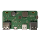
Fully-Integrated Bi-directional PD3.0 and Fast Charge Power Bank SOC with Multiple Input and Output Ports based on IP5328P
Properties
Pricing & Availability
Distributor | Qty 1 |
|---|---|
Arrow | $0.07 |
Digi-Key | $3.15–$5.10 |
LCSC | $7.15 |
Mouser | $6.27 |
TME | $0.64 |
Verical | $0.32–$0.44 |
Controls
Welcome 👋
Flux helps you build PCBs faster with an AI teammate!
Create your account to collaborate, stay updated, fork your own version, and get instant answers from our AI agent.
kaia-yellow140857
copilot