Chat
Welcome to Flux
Treat Flux like your intern. Tell it what you'd like to build and it'll get to work. You can also ask it questions, brainstorm ideas, and teach it your preferences. Learn More
Explain this part
Write a part description
Describe each pin
Operating conditions
Electrical max ratings
Part Specifications
Application circuits
Verify Part Details
Recommend similar parts
Check availability & lifecycle
explain this project.

2y
If you're referring to the maximum operating temperature of the PIC18F25K83-I/SS Microcontroller used in this project, according to Microchip Technology, it's typically between -40°C to +125°C.
However, it's always best to refer back to the specific datasheet of the component for precise specifications, as conditions can vary based on the packaging and grade of the component.
2y
2y
Yes, the PIC18F25K83 microcontroller from Microchip does support Controller Area Network (CAN) communication.
It comes with two CAN modules that conforms to the CAN 2.0B standard, allowing it to both receive and transmit CAN messages, with features like automatic remote frame handling and wake-up from sleep on bus activity. The corresponding pins for CAN communication are typically RC6 (CANRX) and RC7 (CANTX).
Remember that to use the CAN functionality, you will need to appropriately configure the microcontroller using firmware, as per Microchip's datasheets and application notes.
2y
2y
This project is an electronic circuit design involving a Microchip PIC18F25K83 Microcontroller (MCU). It's a high-performance microcontroller with XLP (Extreme Low Power) for enhanced power efficiency. The chip has a clock speed of 64Mhz, 32KB Flash memory, and utilizes a 8-bit architecture.
The microcontroller is in a 28-SSOP (Shrink Small-Outline Package) package style.
The project does not indicate a specific use case or application yet. Given the numerous Input/Output (I/O) options available through the PIC microcontroller, this could potentially be used for a broad range of applications from IoT devices, robotics, home automation, or embedded systems, depending on how the pins are utilized and what additional components are added.
The schematic currently includes the mentioned microcontroller with its 28 pins, each of which have individually been designated in the project, but no other components have been added to the project yet.
Further more, no electrical connections have been made in this project yet. The next step in this project would likely be to decide what peripherals or additional components are needed and how they should be connected to the pins of the microcontroller.
2y
Someone is typing...
2
RB6/ICSPCLK
RC5
RB2
VDD
RB4
RA3
VSS_2
RA6
RB3
RA5
RB7/ICSPDAT
RA7
RC6
RA2
RC7
RB1
RC4
RA1
RA0
RC3
VSS_1
VPP/~MCLR~/RE3
RA4
RB5
RC2
RC1
RB0
RC0
No files yet
Reviews
Documents
Documents are markdown text files which describe project goals, capture details, or even simulation outputs.

PIC18F25K83-I/SS
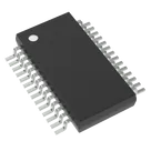
PIC PIC® XLP™ 18K, Functional Safety (FuSa) Microcontroller IC 8-Bit 64MHz 32KB (16K x 16) FLASH 28-SSOP #CommonPartsLibrary #IntegratedCircuit #Embedded #Microcontroller #PIC18F25
Properties
Microcontroller
Microchip Technology
PIC18F25K83-I/SS
U
Pricing & Availability
DPN | Stock | Qty 1 |
|---|---|---|
3 | 0–47 | $2.018–$2.063 |
1 | 0 | $0.00 |
1 | 11 | $4.1627 |
1 | 1.6K | $2.34 |
1 | 47 | $2.36 |
6 | 47–846 | $2.018–$3.8186 |
Controls
Welcome 👋
Flux accelerates your PCB design with AI.
Create your account to start using this component and bring your ideas to life.
davydoung
copilot
MCLR/RE3 pin which typically serves as a programming voltage input/Master Clear (Reset) pin.