Chat
Welcome to Flux
Treat Flux like your intern. Tell it what you'd like to build and it'll get to work. You can also ask it questions, brainstorm ideas, and teach it your preferences. Learn More
Explain this part
Write a part description
Describe each pin
Operating conditions
Electrical max ratings
Part Specifications
Application circuits
Verify Part Details
Recommend similar parts
Check availability & lifecycle
how do I use Flux?

2y
Using Flux, the electronics CAD program, involves several key steps to design electronic circuit schematics and PCB layouts. Here's a general guide to get you started:
- Create a New Project: Begin by creating a new project. This will give you a clean workspace where you can start designing your schematic and PCB layout.
- Design the Schematic:
- Drag components from the library onto the schematic canvas.
- Use wires to connect the components together according to your circuit design.
- Assign values and names to the components as required.
- Validate Your Schematic: Check for any errors or warnings in your schematic. This step helps ensure that your circuit is correctly designed before moving on to the PCB layout.
- Create the PCB Layout:
- Transfer your schematic design to the PCB layout editor.
- Place the components on the board and route the traces to connect the components, following the connections established in the schematic.
- Define the board shape and size, and add any necessary mechanical features or mounting holes.
- Check Design Rules: Use the Design Rule Check (DRC) feature to ensure that your PCB layout meets the specified manufacturing constraints and standards.
- Export Your Design: Once your design is complete and validated, export the necessary files for manufacturing. This typically includes Gerber files for the PCB fabrication and a Bill of Materials (BOM) for the component assembly.
For in-depth tutorials on how to use specific features of Flux, access the documentation page through the help menu or watch video tutorials on YouTube. Additionally, joining the Slack community can be a great way to ask questions and get support from both the Flux team and other users.
Remember, if you need to learn how to use Flux for a specific task or are looking for more detailed instructions, Flux provides comprehensive documentation and support resources:
- Help and Tutorials: The quickest way to jump into Flux and get started on a project. There are in-depth tutorials about how to use Flux and detailed information about the elements of Flux in the documentationd5ea75d6−2108−5c58−ab20−9457cda2a9d8.
- YouTube and Slack Community: Explore video tutorials, crash courses, and communicate with the Flux community for additional support3c8cdc5c−3232−526e−b824−c50d2f9ed0b3.
If you encounter any issues or have specific questions as you start using Flux, don't hesitate to reach out for live support or join the community for advicea9af9cfe−e5f6−5ab9−80b0−238b807fd776.
2y
Someone is typing...
5
New Comment
Someone is typing...
6
No files yet
Reviews


NE555N
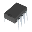
555 Type, Timer/Oscillator (Single) IC 500kHz 8-DIP #Commonpartlibrary #IntegratedCircuit #Timer #Oscillator
Properties
Pricing & Availability
Distributor | Qty 1 |
|---|
Controls
Welcome 👋
Flux accelerates your PCB design with AI.
Create your account to start using this component and bring your ideas to life.
pablo3044
pablo3044
copilot