Chat
Welcome to Flux
Treat Flux like your intern. Tell it what you'd like to build and it'll get to work. You can also ask it questions, brainstorm ideas, and teach it your preferences. Learn More
Explain this part
Write a part description
Describe each pin
Operating conditions
Electrical max ratings
Part Specifications
Application circuits
Verify Part Details
Recommend similar parts
Check availability & lifecycle
give a circuit to get 3.3 V from 5V
make that circuit
2y
2y
To get 3.3V from a 5V power supply for your project using simple components like resistors or more advanced components like linear voltage regulators, the more efficient and reliable method would utilize a voltage regulator. Below, I'll outline two approaches: one using a linear voltage regulator and another basic approach using a resistor voltage divider for low power applications or where precision isn't critical.
Using a Linear Voltage Regulator
A linear voltage regulator is an optimal choice for converting 5V to 3.3V, especially if your circuit demands a stable output. The LD1117V33 is a popular choice for such applications.
-
Parts Needed:
- LD1117V33 or similar 3.3V linear voltage regulator
- A 10μF capacitor (Cin) for the input
- A 10μF capacitor (Cout) for the output to ensure stability
-
Connections:
- Connect your 5V supply to the
Inputpin of the LD1117V33. - Connect a GND line to the
Groundpin of the LD1117V33. - Your regulated 3.3V output will be available at the
Outputpin of the LD1117V33. - Place the input capacitor between the
Inputpin and the GND. - Place the output capacitor between the
Outputpin and the GND.
- Connect your 5V supply to the
For applications with very low current consumption and where voltage stability and efficiency are not critical, you can use a resistor voltage divider. However, this is not recommended for powering anything but the most trivial loads, as the voltage will vary with changes in current draw.
- Parts Needed:
- Resistor R1
- Resistor R2
Given your requirement, assuming a theoretical situation without load, you can select resistor values to create a voltage divider. For practical purposes, I'll explain the calculation, but I recommend the voltage regulator method for most applications.
- Voltage Divider Formula: Vout=Vin×R1+R2R2
Choosing R1 as 1kΩ and solving for R2 to get close to 3.3V:
3.3V=5V×1000+R2R2
Solving for (R2), we get a value that pairs well with a standard resistor value slightly adjusting for common availability, but remember the actual output will very likely not be stable under varying loads.
Assuming theoretical under no-load or fixed-load conditions, a combination like 1kΩ for R1 and approximately 2kΩ for R2 could be used. But again, this method is not generally recommended for powering circuits that require a stable 3.3V supply.
Recommendations
For most applications requiring 3.3V from a 5V source, a linear voltage regulator like the LD1117V33 or similar is the best choice due to its simplicity and reliability in providing a stable output voltage. Voltage dividers are not ideally suited for power conversion but can be used for signal level adjustment or in very low-power, low-precision scenarios.
2y
make this circuit
2y
Given the components and context of your project described earlier, to design a schematic using a linear voltage regulator (LD1117V33 or similar) to step down 5V to 3.3V, here is a direct instruction list. For this scenario, I'm going to assume you're integrating this power regulation section into your existing project with an MPU-6050 sensor and other components outlined previously.
Since you've listed only basic pin designators without specific component designations (like U1 for an IC, C1 for a capacitor), I'll assume some component designators and make up a straightforward connection list. If you're using the Flux.ai tool, you'll draw and place components per these instructions.
Components to Add:
- U1: LD1117V33 (3.3V Voltage Regulator)
- C1, C2: 10μF capacitors (input and output capacitors for the regulator)
Making the Connections:
-
Power Input Preparation:
- If you haven't already, assume a 5V power source is available in your project and label it accordingly.
-
Voltage Regulator Integration:
- Connect VIN to U1:IN. This is your 5V input to the voltage regulator.
- Connect GND to U1:GND (pin 2). This grounds the regulator.
-
Capacitors for Stability:
- Connect C1:1 to U1:IN and C1:2 to GND. This capacitor should be placed close to the input of the regulator.
- Connect C2:1 to U1:OUT and C2:2 to GND. This capacitor should be placed close to the output of the regulator.
-
3.3V Power Output:
- U1:OUT will now provide the regulated 3.3V. You can connect this pin to any components in your circuit that require 3.3V, including the 3.3V input pins of your MPU-6050 module and other 3.3V logic components.
Example Usage with MPU-6050:
- Since the MPU-6050 operates at 3.3V, you will directly connect U1:OUT to the 3.3V power input of your MPU-6050 module. If it is designated as 3Vo in your list, then:
- Connect U1:OUT to 3Vo.
Grounding:
- Ensure that all GND pins in your project, including MPU-6050's GND, are connected together to form a common ground.
By following these steps in Flux.ai, you should be able to route and connect components as instructed to integrate a 5V to 3.3V step-down section into your project. Remember to check connections and verify the schematic for errors or omissions before proceeding to layout PCBs or constructing the circuit physically.
2y
Someone is typing...
2
SCL_EXT
VIN
SDA_EXT
AD0
3Vo
GND
SDA
CLKN
GND
INT
SCL
FSYNC_IN
Reviews
mpu6050 6DOF
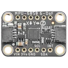
Multiple Function Sensor Development Tools Adafruit MPU-6050 6-DoF Accel and Gyro Sensor - STEMMA QT Qwiic #Module #Sensor #gyro #accelerometer #MPU6050
Properties
module
Adafruit Industries
mpu6050 6DOF
U
Pricing & Availability
Distributor | Qty 1 |
|---|
Controls
Welcome 👋
Flux accelerates your PCB design with AI.
Create your account to start using this component and bring your ideas to life.
porfirios
porfirios
copilot