Treat Flux like your intern. Tell it what you'd like to build and it'll get to work. You can also ask it questions, brainstorm ideas, and teach it your preferences. Learn More
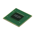
Dividing the MIMX8MQ5DVAJZAB schematic into two sub-blocks involves grouping related functionalities or interfaces. This microprocessor integrates diverse functionalities which can be logically divided for better management, understanding, or even layout purposes on a PCB design. Here's a suggestion for subdividing the schematic based on common grouping practices in electronics design, focusing on separation by function:
Sub-Block 1: Core Processing and Memory Interface
This sub-block focuses on the core processing capabilities of the MIMX8MQ5DVAJZAB and its direct memory interfaces. It includes the ARM® Cortex®-A53 cores, associated power supplies, and the DRAM interface.
Core Components:
ARM® Cortex®-A53 Microprocessor Core
DRAM Interface (DRAM_DQS3_P, DRAM_DQS3_N, DRAM_DQ29, DRAM_DQ14, etc.)
Power Management:
VDD_SOC (VDD_SOC_4, VDD_SOC_18, etc.)
VDD_ARM (VDD_ARM_7, VDD_ARM_12, etc.)
VDD_DRAM (VDD_DRAM_17, VDD_DRAM_12, etc.)
Various VSS pins for grounding.
Sub-Block 2: Peripheral Interfaces and Power Management
This sub-block encompasses the wide range of peripheral interfaces that the MIMX8MQ5DVAJZAB supports, including HDMI, Ethernet, USB, and more. It also covers additional power management details beyond the core voltages.
Dedicated VDD lines for peripherals (VDD_USB, VDD_ETH, etc.)
Power On/Off control (PMIC_ON_REQ, POR_B, etc.)
Grounding specifics (Various VSS pins related to peripherals).
Logical Connections (Hypothetical)
While the project hasn’t specified electrical connections yet, based on the components involved, here’s how connections might typically be organized within each sub-block:
Core Processing and Memory Interface:
Connect VDD and VSS pins appropriately to ensure power integrity for the cores and memory interface.
DRAM memory interface connections require careful impedance matching and routing to ensure signal integrity.
Peripheral Interfaces and Power Management:
Each interface (HDMI, USB, etc.) will have its power supply lines, grounding, and signal lines connected according to the peripheral's requirements.
Power management lines might be connected to external regulators or PMICs controlling the power sequencing for the peripherals.
This division strategy aids in modularizing the design, simplifying troubleshooting, and streamlining the layout process by grouping components with similar design considerations.
2y
Someone is typing...
2
No files yet
Reviews
Documents
Documents are markdown text files which describe project goals, capture details, or even simulation outputs.
sanjay20891
copilot
- ARM® Cortex®-A53 Microprocessor Core
- DRAM Interface (DRAM_DQS3_P, DRAM_DQS3_N, DRAM_DQ29, DRAM_DQ14, etc.)
Power Management:- VDD_SOC (VDD_SOC_4, VDD_SOC_18, etc.)
- VDD_ARM (VDD_ARM_7, VDD_ARM_12, etc.)
- VDD_DRAM (VDD_DRAM_17, VDD_DRAM_12, etc.)
- Various VSS pins for grounding.
Sub-Block 2: Peripheral Interfaces and Power Management- HDMI Interface (HDMI_DDC_SCL, HDMI_DDC_SDA, HDMI_REFCLK_P, HDMI_REFCLK_N, etc.)
- Ethernet (ENET_RXC, ENET_TXC, ENET_RX_CTL, etc.)
- USB (USB2_DN, USB2_DP, etc.)
- SD Interface (SD1_CLK, SD1_CMD, etc.)
- NAND Interface (NAND_READY_B, NAND_CLE, etc.)
- UART Interface (UART1_RXD, UART3_TXD, etc.)
- I2C (I2C1_SCL, I2C4_SDA, etc.)
Power Management:- Dedicated VDD lines for peripherals (VDD_USB, VDD_ETH, etc.)
- Power On/Off control (PMIC_ON_REQ, POR_B, etc.)
- Grounding specifics (Various VSS pins related to peripherals).
Logical Connections (Hypothetical)