Chat
Welcome to Flux
Treat Flux like your intern. Tell it what you'd like to build and it'll get to work. You can also ask it questions, brainstorm ideas, and teach it your preferences. Learn More
Explain project
Write a project description
Find schematic issues
Create a test plan
Simulate a circuit
Prepare for Manufacturing
Component Selection Workflow
New Subsystem Wizard
please explain what U1 does.

1y
The component U1 in your schematic is a MAX2606EUT+T from Maxim Integrated. This part is a VHF/UHF oscillator designed specifically for FM radio transmitter applications. It generates a frequency modulated signal which can be broadcast over FM radio frequencies.
Here's a brief explanation of the pins and their likely connections in an FM transmitter circuit:
-
IND (Pin 1): This pin connects to an external inductor, which together with an internal capacitor, determines the frequency of oscillation.
-
GND (Pin 2): The ground pin for the IC, connected to system ground.
-
TUNE (Pin 3): This pin adjusts the tuning of the oscillator frequency. It can be connected to a resistor network or variable resistor to allow for frequency adjustments.
-
OUT- (Pin 4) & OUT+ (Pin 6): These are differential outputs that provide the frequency modulated signal. The outputs can be connected to an antenna circuit, probably through some matching network.
-
VCC (Pin 5): The power supply pin providing the necessary voltage for the oscillator to function, typically 3.3V or 5V.
The use of U1 in your circuit implies you want to create an FM signal, which can then be transmitted via an antenna (like ANT1) and received by FM radios.
1y
Someone is typing...
5
@copilot, develop an FMEA (Failure Mode and Effects Analysis) report in a table ...

@copilot, develop an FMEA (Failure Mode and Effects Analysis) report in a table format that analyzes the systems schematic, each unique component specification, and operational parameters. It should identify critical failure modes, assess their impact, and recommend mitigation actions based on severity, occurrence probability, and detectability. Include columns such as: process step, potential failure mode, potential failure effect, S, O, D, RPN, Action Recommended, and any other you see fit.
2y
Certainly! Below is a Failure Mode and Effects Analysis (FMEA) report for your FM transmitter project, including the process steps, potential failure modes, their effects, and recommended actions.
Table
| Process Step | Component | Potential Failure Mode | Potential Failure Effect | S (Severity) | O (Occurrence) | D (Detectability) | RPN (Risk Priority Number) | Action Recommended |
|---|---|---|---|---|---|---|---|---|
| Power Supply | U2 | Over-voltage | Damage to components | 9 | 3 | 4 | 108 | Use over-voltage protection, e.g., zener diode |
| Power Supply | U2 | Under-voltage | System malfunction | 7 | 4 | 5 | 140 | Use proper power regulation and capacitors |
| Oscillator | U1 | Frequency drift | Poor transmission quality | 8 | 3 | 6 | 144 | Use high-precision components, add thermal compensation |
| Oscillator | L1 | Inductor open circuit | No signal generation | 10 | 2 | 3 | 60 | Use quality inductors, conduct thorough testing |
| Oscillator | C5 | Capacitor failure | Unstable frequency | 8 | 3 | 5 | 120 | Use high-quality, low ESR capacitors |
| Modulator | MK1 | Microphone failure | No audio input | 7 | 2 | 2 | 28 | Choose robust microphones, run diagnostics |
| Modulator | R4 | Resistor value change | Incorrect tuning | 6 | 3 | 5 | 90 | Select precision resistors, in-circuit testing |
| RF Output | ANT1 | Antenna disconnect | No signal transmission | 8 | 2 | 4 | 64 | Secure connections, inspect connectors |
| General | Any | Solder joint failure | Intermittent connections | 9 | 4 | 3 | 108 | Quality soldering, visual and X-ray inspection |
| General | Entire Circuit | EMI/RFI interference | Signal distortion | 7 | 4 | 2 | 56 | Proper shielding, layout optimization |
| General | Entire Circuit | Thermal issues | Component damage | 9 | 3 | 3 | 81 | Thermal management, use heat sinks |
- Process Step: The stage or component in the system being analyzed.
- Component: Specific component in the schematic, represented by its designator and part number.
- Potential Failure Mode: The way in which the component could potentially fail.
- Potential Failure Effect: The impact on the overall system caused by the failure mode.
- S (Severity): Ranked from 1 (least severe) to 10 (most severe).
- O (Occurrence): The likelihood of the failure mode occurring, ranked from 1 (least likely) to 10 (most likely).
- D (Detectability): The likelihood of detecting the failure before it causes harm, ranked from 1 (most likely to detect) to 10 (least likely to detect).
- RPN (Risk Priority Number): Calculated as RPN=S×O×D.
- Action Recommended: Suggested action to mitigate the risk.
Feel free to modify or add more components and failure modes as needed.
2y
Someone is typing...
3
create a high level mermaid block diagram of this project. Include key component...

1y
Here's a high-level mermaid block diagram of your FM transmitter project, featuring key components and their manufacturer part numbers.
Diagram
This diagram displays the main components of your FM transmitter project and their connections. Let me know if there's anything you'd like to adjust or focus on!
1y
Someone is typing...
6
create a high level mermaid block diagram of U1. Include key component's manufac...
1y
Here is a Mermaid block diagram for the MAX2606EUT+T, which is your FM transmitter IC.
Diagram
This diagram shows the pin connections for the MAX2606EUT+T. There is:
- VCC connected to Pin 5 for power supply.
- OUT+ and OUT-, represented by Pins 6 and 4, connected to the antenna circuit.
- TUNE at Pin 3 for frequency adjustment, possibly connected to a potentiometer or a digital control circuit.
- IND to which an external inductor is connected, used for frequency stabilization.
- GND at Pin 2, which should be connected to the ground plane of your PCB.
Let me know if you need more details or modifications!
1y
Someone is typing...
4
New Comment
Someone is typing...
5
ANT1
U2
R4
Resistance
100kΩ
L1
Inductance
390nH
MK1
U1
C1
Capacitance
2.2uF
R1
Resistance
1KΩ
3V3
TUNEPAD
VCC
R2
Resistance
1KΩ
C5
Capacitance
100pF
C4
Capacitance
1nF
R3
Resistance
500 Ω
C3
Capacitance
2.2uF
GND
No files yet
Reviews
Documents
Documents are markdown text files which describe project goals, capture details, or even simulation outputs.
Assets

FM TRANSMITTER.PNG
FM TRANSMITTERThumbnailFM Transmitter
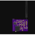
An FM transmitter allows a phone to broadcast music stored in its memory on FM frequencies, so that it can be tuned into a nearby FM receiver such as a a car radio.
Properties
Properties describe core aspects of the project.
Pricing & Availability
Distributor | Qty 1 |
|---|---|
Digi-Key | $3.47–$5.63 |
LCSC | $1.89–$2.49 |
Mouser | $5.58 |
Controls
Welcome 👋
Flux helps you build PCBs faster with an AI teammate!
Create your account to collaborate, stay updated, fork your own version, and get instant answers from our AI agent.
kasenge1
copilot
-
Antenna (ANT1):
- Pin: ANT_IN
- Purpose: Transmits the FM signal generated by the circuit.
- Connections:
- Connect ANT1:ANTIN to C5:P1.
-
Voltage Regulator (U2):
- Part Number: AP2210N-3.3TRG1
- Purpose: Provides stable 3.3V output required by other components.
- Pins: VIN, GND, VOUT
- Connections:
- Connect U2:VIN to power source.
- Connect U2:VOUT to R4:P1, R3:P1, C1:P2, U1:VCC, R2:P1, R1:P2.
- Connect U2:GND to C1:P1.
-
FM Oscillator (U1):
- Part Number: MAX2606EUT+T
- Purpose: Generates and modulates the FM signal.
- Pins: IND, GND, TUNE, OUT-, VCC, OUT+
- Connections:
- Connect U1:IND to L1:P2.
- Connect U1:GND to GND.
- Connect U1:TUNE to R4:P3, C3:P1, C4:P1.
- Connect U1:OUT− to R2:P2.
- Connect U1:OUT+ to R1:P1, C5:P2.
- Connect U1:VCC to the 3.3V rail.
-
Microphone (MK1):
- Part Number: POM-3042P-R
- Purpose: Captures audio signals to be transmitted.
- Pins: N, P
- Connections:
- Connect MK1:N to GND.
- Connect MK1:P to C3:P2.
Supporting Components-
Resistors:
- R1: 1K ohm:
- Connect R1:P1 to U1:OUT+.
- R2: 1K ohm
- Connect R2:P1 to the 3.3V rail.
- R3: 500 ohm
- Connect R3:P1 to the 3.3V rail.
- R4: 100K potentiometer
- Connect R4:P1 to the 3.3V rail.
- Connect R4:P2 to GND.
-
Capacitors:
- C1: 2.2μF
- Connect C1:P2 to the 3.3V rail.
- Connect C1:P1 to GND.
- C3: 2.2μF
- Connect C3:P1 to R4:P3.
- Connect C3:P2 to R3:P2.
- C4: 1nF
- Connect C4:P1 to the tuning circuit.
- C5: 100pF
- Connect C5:P1 to ANT1.
-
Inductor (L1):
- Part Number: AISC-0805-R39J-T
- Inductance: 390nH
- Purpose: Forms part of the oscillator circuit.
- Connections:
- Connect L1:P1 to GND.
- Connect L1:P2 to U1:IND.
Power and Ground Connections