Chat
Welcome to Flux
Treat Flux like your intern. Tell it what you'd like to build and it'll get to work. You can also ask it questions, brainstorm ideas, and teach it your preferences. Learn More
Explain this part
Write a part description
Describe each pin
Operating conditions
Electrical max ratings
Part Specifications
Application circuits
Verify Part Details
Recommend similar parts
Check availability & lifecycle
i need to create a clap switch project with 8051 microcontroller which turn the ...

2y
To design a clap switch project using the AT89S51 microcontroller that toggles an LED based on the clap pattern, you'll need a few external components in addition to your microcontroller:
- Microphone amplifier circuit (to detect claps)
- LED (for visual indication)
- Debouncing circuit (optional, but recommended to filter out noise from the clap sound)
- General components like resistors, capacitors, and a voltage regulator.
Use an electret microphone coupled with an amplifier (such as the LM358) to convert the sound of claps into electrical signals. This circuit should convert the clap into a sharp pulse. Connect the output of this circuit to a digital pin on the microcontroller - considering pin
2. LED Connection
P1.0.- Connect an LED (let's designate it as
LED1) with a current limiting resistor (designate itR1) in series, to one of the microcontroller’s output pins, for example,P1.1.
The debouncing circuit can be a simple low pass filter or a software debouncing code in your microcontroller to filter out noise and false triggers.
4. Program Logic
- The program running on the microcontroller should continuously monitor the input from the microphone amplifier circuit.
- When a clap is detected (a high pulse), the software should check the interval between claps:
- Single Clap: Toggle the LED state.
- Two Consecutive Claps: Keep the LED in the same state or implement a different functionality as per your preference.
- Microphone Amplifier to Microcontroller:
- Assume the amplifier circuit gives a digital output; connect this output to
P1.0.
- Assume the amplifier circuit gives a digital output; connect this output to
- LED Circuit:
- Connect
LED1:anodetoP1.1. - Connect
R1:one endtoLED1:cathodeandR1:other endtoGND.
- Connect
-
Design the Microphone Amplifier Circuit. This is external to the AT89S51 and can be designed on a breadboard or as part of your PCB.
-
Connect the Amplifier Output to P1.0. (Assuming P1.0 is configured as an input in your software.)
- For connecting circuits external to the AT89S51, note that we are assuming connections above. Modify your connections according to your actual external circuit design.
-
Write the Software:
- Initialize
P1.0as input (for the microphone amplifier output). - Initialize
P1.1as output (for the LED). - Continuously poll
P1.0to detect a clap (signal from the microphone amplifier). - Use a timer to measure the interval between claps.
- Toggle the state of the LED connected to
P1.1based on the number of claps detected within a specified time frame.
- Initialize
- Use interrupts for better efficiency in detecting clap signals.
- Debounce both the clap signal and button inputs if necessary.
- Consider power supply requirements, especially if using a breadboard for the microphone amplifier and debouncing circuits.
- Software debouncing might require you to fine-tune delays to effectively differentiate between one and two claps.
This outline provides a foundation for your clap switch project. You'll need to adjust details based on the exact components used and their specifications. Good luck with your clap switch project!
2y
Someone is typing...
4
create a high level mermaid block diagram of this project. Include key component...
2y
To create a high-level mermaid block diagram of your project, we'll summarize the key components and their respective pins. Here is a generic example of how you might structure the diagram based on the AT89S51-24PU microcontroller and its connections.
Note: Mermaid diagrams use a specific syntax for generating visuals. The description provided here outlines the hierarchical structure and connections in a way that can be adapted to mermaid or similar diagramming tools.
graph TD;
    AT89S51[AT89S51-24PU Microchip Technology]
    P0[Port 0]
    P1[Port 1]
    P2[Port 2]
    P3[Port 3]
    XTAL[Crystal Oscillator]
    GND[GND]
    VCC[VCC]
    RST[Reset - RST]
    ALE_PROG[ALE/$PROG]
    $EA_VPP[~EA~$/VPP]
    $PSEN[~PSEN]

    AT89S51 -- P0.0_$AD0$ --> P0;
    AT89S51 -- P0.1_$AD1$ --> P0;
    AT89S51 -- P0.2_$AD2$ --> P0;
    AT89S51 -- P0.3_$AD3$ --> P0;
    AT89S51 -- P0.4_$AD4$ --> P0;
    AT89S51 -- P0.5_$AD5$ --> P0;
    AT89S51 -- P0.6_$AD6$ --> P0;
    AT89S51 -- P0.7_$AD7$ --> P0;
    AT89S51 -- P1.0 --> P1;
    AT89S51 -- P1.1 --> P1;
    AT89S51 -- P1.2 --> P1;
    AT89S51 -- P1.3 --> P1;
    AT89S51 -- P1.4 --> P1;
    AT89S51 -- $MOSI$_P1.5 --> P1;
    AT89S51 -- $MISO$_P1.6 --> P1;
    AT89S51 -- $SCK$_P1.7 --> P1;
    AT89S51 -- P2.0_$A8$ --> P2;
    AT89S51 -- P2.1_$A9$ --> P2;
    AT89S51 -- P2.2_$A10$ --> P2;
    AT89S51 -- P2.3_$A11$ --> P2;
    AT89S51 -- P2.4_$A12$ --> P2;
    AT89S51 -- P2.5_$A13$ --> P2;
    AT89S51 -- P2.6_$A14$ --> P2;
    AT89S51 -- P2.7_$A15$ --> P2;
    AT89S51 -- $TXD$_P3.1 --> P3;
    AT89S51 -- $RXD$_P3.0 --> P3;
    AT89S51 -- $INT0$_P3.2 --> P3;
    AT89S51 -- $INT1$_P3.3 --> P3;
    AT89S51 -- $T0$_P3.4 --> P3;
    AT89S51 -- $T1$_P3.5 --> P3;
    AT89S51 -- $WR$_P3.6 --> P3;
    AT89S51 -- $RD$_P3.7 --> P3;
    AT89S51 -- XTAL1 --> XTAL;
    AT89S51 -- XTAL2 --> XTAL;
    AT89S51 -- GND --> GND;
    AT89S51 -- VCC --> VCC;
    AT89S51 -- RST --> RST;
    AT89S51 -- ALE_PROG --> ALE_PROG;
    AT89S51 -- $EA_VPP --> $EA_VPP;
    AT89S51 -- $PSEN --> $PSEN;
This example assumes a hierarchy where the AT89S51-24PU microcontroller is the central component, and all peripheral connections (i.e., ports, GND, VCC, etc.) branch off from it. Please adapt the syntax and connections based on the specific details of your project and how you plan to structure the components within the mermaid diagramming tool or another visual representation tool you might use.
Remember, this is a simplified textual representation to guide your diagram creation, focusing on the hierarchical structure rather than the physical layout of connections.
2y
Someone is typing...
3
can you create the block diagram of the clap switch project
can you create the block diagram of the clap switch project
2y
Someone is typing...
5
(TXD)_P3.1
ALE/~PROG
P2.6_(A14)
P1.1
(~WR)_P3.6
(RXD)_P3.0
(~INT0)_P3.2
XTAL1
P1.4
P0.3_(AD3)
P2.7_(A15)
P0.6_(AD6)
P2.0_(A8)
P2.2_(A10)
P2.5_(A13)
P0.5_(AD5)
XTAL2
GND
P0.4_(AD4)
P2.4_(A12)
(SCK)_P1.7
P2.1_(A9)
(~RD)_P3.7
P0.2_(AD2)
~PSEN
(T1)_P3.5
P1.0
(T0)_P3.4
(~INT1)_P3.3
P1.2
(MOSI)_P1.5
P0.7_(AD7)
RST
P2.3_(A11)
(MISO)_P1.6
P0.1_(AD1)
P1.3
~EA~/VPP
P0.0_(AD0)
VCC
No files yet
Reviews
Documents
Documents are markdown text files which describe project goals, capture details, or even simulation outputs.

AT89S51-24PU
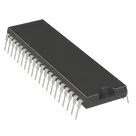
8051 89S Microcontroller IC 8-Bit 24MHz 4KB (4K x 8) FLASH 40-PDIP #CommonPartsLibrary #IntegratedCircuit #Embedded
#Microcontroller
#AT89S51
Properties
AT89S51-24PU
Microchip Technology
IC
Integrated Circuit
Pricing & Availability
DPN | Stock | Qty 1 |
|---|---|---|
4 | 3–2.4K | $2.8143–$3.638 |
1 | 0 | $0.00 |
1 | 13 | $4.28292 |
1 | 33 | $5.0524 |
1 | 2.1K | $3.32 |
1 | 10 | $4.85 |
13 | 3–2.6K | $2.816–$4.5271 |
Controls
Welcome 👋
Flux accelerates your PCB design with AI.
Create your account to start using this component and bring your ideas to life.
vprec
copilot