Chat
Welcome to Flux
Treat Flux like your intern. Tell it what you'd like to build and it'll get to work. You can also ask it questions, brainstorm ideas, and teach it your preferences. Learn More
Explain this part
Write a part description
Describe each pin
Operating conditions
Electrical max ratings
Part Specifications
Application circuits
Verify Part Details
Recommend similar parts
Check availability & lifecycle
caan you write a c code for it where it will take commands ' f ' , ' b' which is...

2y
Certainly! Based on your project description with the AT89C51 microcontroller, I'm going to assume you plan to control a motor or similar device to move in forward or backward directions based on the commands 'f' and 'b', respectively. For simplicity, I'll assume you might use one of the GPIO (General Purpose Input Output) ports to send signals to control the direction. However, since there's no specific detail about the motor control interface (e.g., H-Bridge, motor driver IC, etc.), I'll keep the code generic. You can adapt the GPIO toggling part as per your specific hardware setup.
In this example, let's use port P1 for demonstration purposes, where setting P1 to a certain value would control the direction.
Here's a simple C code snippet for the AT89C51 microcontroller:
C
#include <reg51.h> // Include the register definitions for the AT89C51 #define FORWARD 0x01 // Assume FORWARD operation sets P1.0 HIGH #define BACKWARD 0x02 // Assume BACKWARD operation sets P1.1 HIGH void delay(unsigned int count) { while(count--) {} } void main(void) { char receivedCommand; TMOD = 0x20; // Use Timer 1, mode 2 (auto-reload) for serial communication TH1 = 0xFD; // Set baud rate to 9600 bps (assuming 11.0592MHz crystal) SCON = 0x50; // Configure serial port in mode 1 (8-bit UART) TR1 = 1; // Start Timer 1 P1 = 0x00; // Initially, no direction is set while(1) { // Check if there is data received in the serial buffer if (RI) { receivedCommand = SBUF; // Read the received data RI = 0; // Clear the receive interrupt flag switch(receivedCommand) { case 'f': P1 = FORWARD; // Set P1 to drive forward break; case 'b': P1 = BACKWARD; // Set P1 to drive backward break; default: P1 = 0x00; // Unknown command, stop or no action break; } } delay(10000); // Simple delay } }
Key Points in the Code:
-
Serial Communication Initialization: The code snippet initializes UART (Universal Asynchronous Receiver/Transmitter) for serial communication with predefined baud rate settings. It assumes an 11.0592 MHz crystal oscillator for the AT89C51 microcontroller, a common setup for achieving accurate baud rates like 9600.
-
Command Handling: The microcontroller continuously listens for incoming serial data. Upon receiving a character, it checks if the character is 'f' or 'b', and sets GPIO port P1 accordingly. I've used simple
FORWARDandBACKWARDmacros to represent action commands, merely as placeholders. Depending on your motor driver or control method, you'll need to modify the implementation of setting P1. -
Delay Function: A rudimentary delay function is used. It's usually more effective to use timer interrupts for precise timing, but for demonstration purposes, this should suffice.
Remember, to implement this for real-world use, you'd need to adjust the GPIO settings according to your hardware design specifics. If you're using a motor driver or an H-Bridge, the connections from P1 to the driver and the driver's control logic will greatly influence how you should write these parts of the code.
2y
Someone is typing...
4
how do I use Flux?
Which line are internal pull ups are conncetd
2y

2y
Flux is an online tool designed for creating and designing electronic circuit schematics and PCB layouts. Here are some general steps on how you can use Flux:
-
Create a New Project: Click on "New Project" to start a new schematic or PCB layout. You will be asked to enter a name for your project.
-
Place Components: In the schematic editor, you can drag and drop components from the library onto the canvas.
-
Connect Components: Draw wires between the different pins of your components to make electrical connections.
-
Assign Footprints: After drawing your schematic, you need to assign footprints to your components for the PCB layout.
-
Design PCB Layout: In the PCB layout editor, you can arrange the components on your board, route tracks, and add other board components like vias and mounting holes.
-
Export for Manufacturing: Once you've verified your design, you can export the necessary files for manufacturing your PCB.
For more in-depth tutorials and guidance, Flux provides multiple resources:
-
Documentation: Refer to the tutorials and reference sections for detailed instructions and tips for using Flux[1].
-
YouTube: There's a library of video tutorials, crash courses, and much more[2].
-
Slack Community: Join the Flux community on Slack to communicate with Flux's team and other active users[3].
-
Live Support: If you have any problems, you can contact the Flux team directly [4].
Remember, it's okay to make mistakes and experiment when using Flux. As you explore and learn, you'll become more proficient in utilizing all of its features! Always feel free to ask for help if you need it.
2y
The Schematic Editor is a key component of Flux, where you build and simulate circuit schematics. Here's how you can find and use the Schematic Editor in Flux:
-
Accessing the Schematic Editor: When you open Flux and start a new project or open an existing one, you're typically taken directly to the Schematic Editor. This area is designed for you to create your electronic schematic diagrams.
-
Main Areas of the Schematic Editor:
- Library Panel: Locate this on the left sidebar. This section houses all the available parts and submodules. You can search through or browse the categories to find the components you need for your design[1].
- Canvas: The central area or canvas is where you drag components from the library and place them to create your schematic. It offers a workspace where you can arrange components and draw connections or wires between them to form your electronic circuit[2].
- Inspector or Properties Menu: Located on the right side, this panel shows contextual information about the selected component or element. It can display properties, pricing, availability, and other relevant metadata. This section helps with configuring component parameters and provides valuable insights while designing[3].
-
Utilizing the Schematic Editor:
- Placing Components: Drag components from the library and drop them onto the canvas. You can use the search function in the library to quickly find specific components.
- Connecting Components: Use the wire tool or simply click on component pins to start drawing wires to make electrical connections between different components.
- Editing Properties: Select a component and use the inspector on the right side to edit properties such as values, package types, and names.
-
Real-Time Synchronization and Collaboration: One of the unique features of Flux is its real-time synchronization to the cloud. This means any changes you make are saved automatically, and if working in a team, everyone can see updates live[4].
To get the most out of the Schematic Editor, explore each of its sections, and don't hesitate to experiment with placing and connecting components. The editor is designed to be intuitive for both beginners and experienced users coming from other electronic design automation (EDA) tools.
2y
where is schematic editor ?
2y
To add an object to your schematic in Flux, follow these general steps:
-
Open Your Project: Ensure that you're in the schematic editor by opening your project within Flux.
-
Access the Library: Locate the Library panel on the left side of your screen. The Library is your go-to place for finding all the parts and objects needed for your schematic[1].
-
Search for a Component: In the Library, you can either browse through the categories or use the search bar to find a specific component or object you want to add to your schematic.
-
Place the Component: Once you have found the component, drag it from the Library panel and drop it onto the schematic canvas at the desired location. You can adjust its position later if needed.
-
Adding Terminals: For creating custom parts or adding specific interfaces to your schematic, you might need to add terminals. Navigate to the library, search for "Terminal," and drag the required number of terminals into your schematic. This is essential for parts like resistors, capacitors, transistors, and more, as they interact through these terminals with other components[2].
After placing the object on your schematic, you can select it to view and edit its properties in the inspector panel on the right side. This includes specifying values, setting part numbers, and other pertinent attributes relevant to your design. Remember, placing and connecting components wisely is crucial for ensuring the functionality and reliability of your electronic design.
2y
how to add object on schematic ?
2y
Someone is typing...
2
No files yet
Reviews

AT89C51
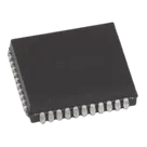
80C51 AT89C CAN Microcontroller IC 8-Bit 40MHz 64KB (64K x 8) FLASH 44-PLCC (16.6x16.6) #CommonPartsLibrary #IntegratedCircuit #Microcontroller
Properties
Microcontroller
Microchip
AT89C51
U
Pricing & Availability
No results found.
Controls
Welcome 👋
Flux accelerates your PCB design with AI.
Create your account to start using this component and bring your ideas to life.
amit2304b
copilot
- The
Notes:#include: This includes the register definitions for the AT89C51 microcontroller, allowing us to use named registers likeP1for operations.void main(void): The entry point for the program. It contains an infinite loop that toggles the state of pin P1.0 (connected to an LED in our hypothetical scenario) and then calls a delay to make the toggling visible as blinking.P1 ^= 0x01;: This line toggles the least significant bit of Port 1 (P1.0). The^=operator is a bitwise XOR assignment that effectively toggles the bit.delay(30000);: This calls a simple delay function that loops a specified number of times to create a pause. Adjust the delay amount (30000in this case) based on your needs for the LED blink rate.delayfunction takes an unsigned integer and loops that many times. The loop is empty because its purpose is just to consume time.P1.0pin.