The enclosure revision failed as a verification artifact, not necessarily because the overall v2c enclosure concept is wrong. The generated views were not reliable enough to prove that the selected parts, cables, and service motions physically fit, so I did not use them to authorize PCB changes.
What is resolved
The UI architecture is now clear:
The OLED and pushable encoder will share J9’s 3V3, GND, I2C_SDA, and I2C_SCL.
A smart I²C encoder avoids adding raw encoder A/B/push connections to the PCB.
The approved visual direction remains the screw-joined translucent enclosure with exposed controls, a guarded tube hatch, and a removable rear panel.
What remains unresolved
OLED mounting
The candidate OLED PCB is about 29.2 × 26.7 mm.
The existing 36 × 24 mm opening is too large to retain it directly.
It therefore needs a carrier or bezel with verified screw locations, display alignment, panel thickness, and cable clearance.
That bezel would be visible, so it must be shown accurately before changing the detailed enclosure.
Encoder mounting
The encoder electronics are suitable in principle, but the complete mechanical stack is not qualified.
We need to verify the threaded bushing, washers and nut, panel opening, 3 mm panel thickness, remaining shaft length, knob engagement, and push-button travel.
Without this, the knob might rub the panel, sit too far out, or lose its push function.
Rear power inlet
A specific threaded panel-mount DC jack still needs to be fixed.
Its cutout, anti-rotation feature, nut clearance, solder-terminal depth, plug overmold, cable bend radius, and disconnect arrangement must fit the removable rear panel.
Rear-panel removal must not pull directly on solder joints or require cutting wires.
Heater and thermal wiring
The heater block and tube holder are custom mechanical assemblies, not components already represented on the PCB.
The exact heater cartridge, block dimensions, thermal cutoff mounting, NTC packaging, thermocouple junction, strain relief, and thermal isolation still need qualification.
The proposed fine thermocouple wire is not directly compatible with the existing JST-XH contact range, which expects substantially larger conductors. A mechanically sound transition is required.
Cable and service sweeps
We have not yet demonstrated that all plugs can be inserted and removed.
Cable bends must avoid the PCB, supports, hatch, optical chamber, and hot surfaces.
The rear panel must be removable with sufficient service slack.
The PCB/base assembly must remain removable without trapping the UI, power, heater, or sensor harnesses.
Why PCB routing is still on hold
The connector positions determine where the harnesses enter the enclosure and how much bend space they require. If one of those connectors needs to move after routing cleanup, the newly routed copper may need to be discarded.
Once those positions are mechanically frozen, I can make a surgical cleanup around U5, R9, R10, and D4 while preserving unrelated copper. That work will particularly address the wide HEATER_LOW_SIDE trace passing R10 with only about 0.36 mm local copper separation. It technically passes the present clearance rule, but it is poor margin in a noisy switching area.
So the current status is: the electrical UI strategy is selected, but the exact mounting and harness geometry are not yet proven. The PCB has deliberately been left unchanged until that proof is available.
On 2026-09-23 the user agreed to the recommended FDM profile: translucent PETG for the visible panels, black PETG for the opaque guarded chamber, 0.4 mm nozzle. Nominal 0.20 mm layer height is a provisional starting point; printer/build volume and fit calibration are unknown, so test coupons and build-volume verification are still required. Refine v2c geometry, not a new silhouette. Do not claim the heater/tube/optics/OLED/encoder/power-inlet interfaces fit a real product until selected parts and drawings or measurements exist.
Revision date: 2026-09-23. v2c supersedes v2b and v2. Adopted requirement: unscrew the whole rear panel for infrequent service/programming rather than adding a service extension. v2c directly edits the existing v2b Build123d source, not PNG-derived geometry. The original flat screw-joined translucent-panel styling, opaque guarded chamber, front controls and live 100 × 100 mm PCB are preserved. On 2026-09-23 the user explicitly replied "yes, looks good" to the v2c view/approval request; v2c is now the approved visual reference for subsequent detailed design. This approval covers appearance and access intent only, not exact fit, safe-touch behavior, manufacturability, or a printable release.
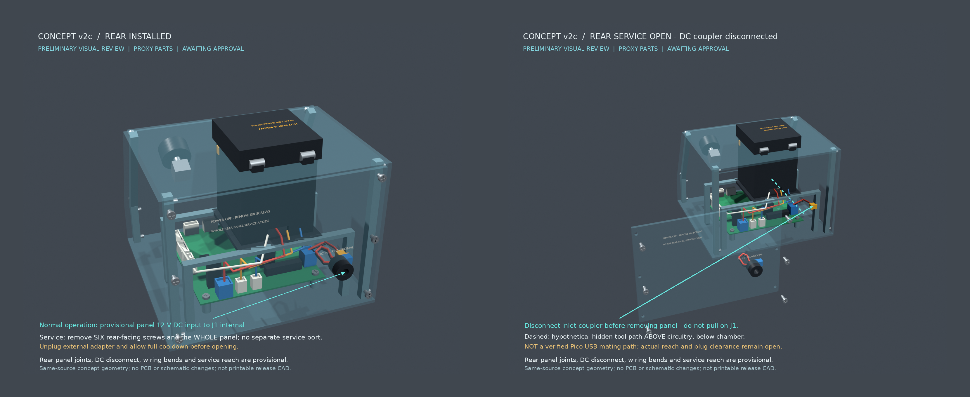
Removed the rear service extension harness, separate service plate, dedicated 55 × 32 mm service aperture and their labels. The whole 154 × 3 × 112.1 mm rear panel is removable; six representational screw heads face rearward (+Y), at x±73, z−5/44/93, with head centers y76. The panel top is z100.1, nominally 0.5 below the roof underside z100.6, to allow normal withdrawal. These dimensions demonstrate intent, not final thread engagement, fastening, tolerance or tool qualification.
The separate provisional panel-mounted 12 V DC inlet remains at (−48,75,25), wired to J1 internal, not substituted for J1 or presented as the Pico USB connector. A provisional two-pole inline disconnect and paired slack pigtail allow the inlet to travel with the panel. The fixed half is centered (−56,61,25); the panel half is (−56,67,25). The approximately 56.13 mm segmented pigtail centerline illustrates slack only, not a usable withdrawal-distance or bend-radius guarantee.
Concept service sequence: unplug the external adapter, allow full cooldown, remove the six rear-facing screws, withdraw the panel cautiously only as the real harness permits, disconnect the internal DC coupler, then remove the whole panel without pulling on J1. The service-open pose assumes the coupler is already unplugged. The panel, inlet, loose pigtail and unplugged half are translated (110,85,0); the screws are translated (110,110,0). Roof, sides, front controls, PCB and small tube hatch remain installed in this service view. Actual connector selection, polarization, retention, strain relief and safe slack length remain open.
Normal tube access is independent: hatch-only open rotates the small opaque hood 105° and changes no panel position. The v2b protective deck, raised sealed cap, optical passage proxies, hot-block warning and coherent OLED states are retained. The exploded view separates the whole rear panel rather than a small cover; it is an assembly illustration, not the normal service or insertion pose.
Source-bound numerical checks — millimeters
Table
Check
v2c result
Meaning and limit
Live board and holes
100 × 100 × 1.29936; top z0; Ø3.4 at (±44,±44)
Unchanged deterministic proxy tied to live layout; no PCB/schematic mutations
Installed bounds
x±80; y−79.864…81; z−14.4…118.5
Overall 160 × 160.864 × 132.9, including protrusions; base160 ×150
Native source compilation
132 solids, 831 faces; locally all solids valid
Multi-part visual review assembly, not a one-piece print
Legacy service extension/plate
No matching solids remain
Names and source geometry checked; old labels removed from current views
Former service aperture
5280 mm³ material, equal to55 ×32 ×3
Former aperture fully filled; only DC inlet and representational screw holes remain
Rear-facing screwdriver approaches
Six Ø10 ×40 cylinders, +Y from y77
No intersection with other modeled solids; not selected-driver or hand clearance
Panel normal withdrawal
+Y0…35, every5
No checked interference with static geometry
Disconnected full rear assembly withdrawal
+Y0…85 every5, then +X10…110 every10 at y85
Zero checked interference for panel, inlet, pigtail and unplugged half; wire flexibility not simulated
Concept approach above U1
Ø10 path at z25; length130.44
No interference against selected proxies; ends above circuitry, not at a mating face
Concept approach above J9 / J10
Ø10 paths at z25; lengths170.53 /187.46
Same limited long-tool/inspection check; not finger reach or cable insertion
Rear inner face to approximate USB region
y72 to approximately y−46:118 depth
Emphasizes reach uncertainty; USB region is not a verified port datum
Cap grip / cap-to-closed-hood clearance
5 /4.5
Preserved v2b geometry; cap top8 above guide
Hatch and axial tube samples
105° hatch;40 axial travel
Rerun checked samples show zero interference; not continuous motion or actual part-fit qualification
Conditional +Y harness headroom
underside42 − assumed connector12 =30
Unchanged; mated plugs, actual body heights and harness bends unresolved
The access centerlines enter near (−37,80,25), run to (−37,−30,25), then toward volumes above U1 or J9/J10. J9/J10 modeled body centers are (12.75,−45.525) and (29.75,−45.525); U1 live placement origin is approximately (−18,−22.476). These checks establish a plausible long-tool/inspection volume beneath the chamber in this sparse proxy assembly, not that removing the rear panel exposes the native USB jack, that the jack is directly reachable, or that a USB cable can mate. The dashed render annotation is a hypothetical hidden path, not a visible connector or extension harness. Actual U1 USB face/axis, plug overmold, fully populated-board obstacles, fingers and cable manipulation remain unverified; another panel may ultimately require removal.
Evidence, assumptions and scope disposition
All five views tessellate the same v2c Build123d assembly; the comparison combines the two rear views. Evidence includes render/tessellation/annotation/validation scripts, cameras, presentation transforms and numerical results. Views are separately framed, not a scale-comparison drawing. Single views1660 ×1360; rear comparison3320 ×1360. Final luminance mean/std: closed78.27/21.96, hatch81.80/31.20, exploded75.10/20.68, rear installed77.09/22.34, rear service-open73.82/18.63, comparison75.45/20.63; no detected border clipping. Every view was visually inspected, including the service-open view separately. Durable image/evidence assets were read back after saving; native source compilation also succeeded.
Table
Assigned v2c item
Disposition
Continue v2b source; remove service extension, plate, aperture and labels
COMPLETED
Whole removable rear panel with outward-facing screw positions
COMPLETED at concept level; sampled approach/removal checks clear
Separate provisional panel DC inlet with disconnect/slack provision
COMPLETED as visual geometry; selected-part wiring/retention qualification UNATTEMPTED
Preserve PCB, front controls, flat panels, opaque guard and independent hatch
COMPLETED; electronics and layout left unchanged
Closed, hatch-only, exploded, rear installed/service-open views and comparison
COMPLETED; saved and inspected
Reasonable concept approach volume toward service circuitry
COMPLETED only for stated proxy cylinders ending above circuitry
Actual native USB reach and cable mating
UNATTEMPTED / unresolved; blocked by missing true port, plug and populated-assembly geometry
Record, supersession, asset links and evidence
COMPLETED
Detailed printable CAD, final fastening, FDM, thermal/safe-touch and optical qualification
No unresolved tool failure blocks the delivered artifacts. The Files editor could not be opened because the requester frontend session was unavailable; assets and this record were saved independently. Native compiler floating-solid/support findings are noteworthy for a multi-part installed assembly and do not imply printable readiness. No electronics, net, PCB placement, board outline, stackup or layout-model nodes were changed. v2c was explicitly visually approved on 2026-09-23; overall enclosure/service engineering is not complete.
Archived concept v2b — SUPERSEDED by v2c
The following v2b section is historical. Its rear service extension, small service plate/aperture and approval request are superseded by v2c above. Its protected-cap concept is retained, subject to the same unverified fit and thermal limitations.
Revision date: 2026-09-23. v2 is superseded following the independent review verdict REVISE. v2b edits the existing v2 Build123d source; it was not reconstructed from PNGs. The approved flat screw-joined translucent-panel visual direction, live PCB frame and electronics are retained. This is preliminary visual geometry only, not detailed printable CAD, a safe-touch qualification or a thermal-performance claim. Text feedback or a marked-up screenshot may be used for the next revision; explicit v2b visual approval is required before detailed CAD.
The v2 problem was real: its tube ended below the small guide, and the block perimeter was not fully guarded. v2b replaces that small guide with a 49 × 49 mm protective deck, covering the 30 × 30 mm hot block top and edges inside the opaque chamber, with only an Ø8.5 mm tube passage. A narrow central sleeve extends down to z98.5; the deck spans z100…103, above the block top z98. The existing chamber walls guard the block sides. This is geometric shielding, not a certified finger probe or spill test.
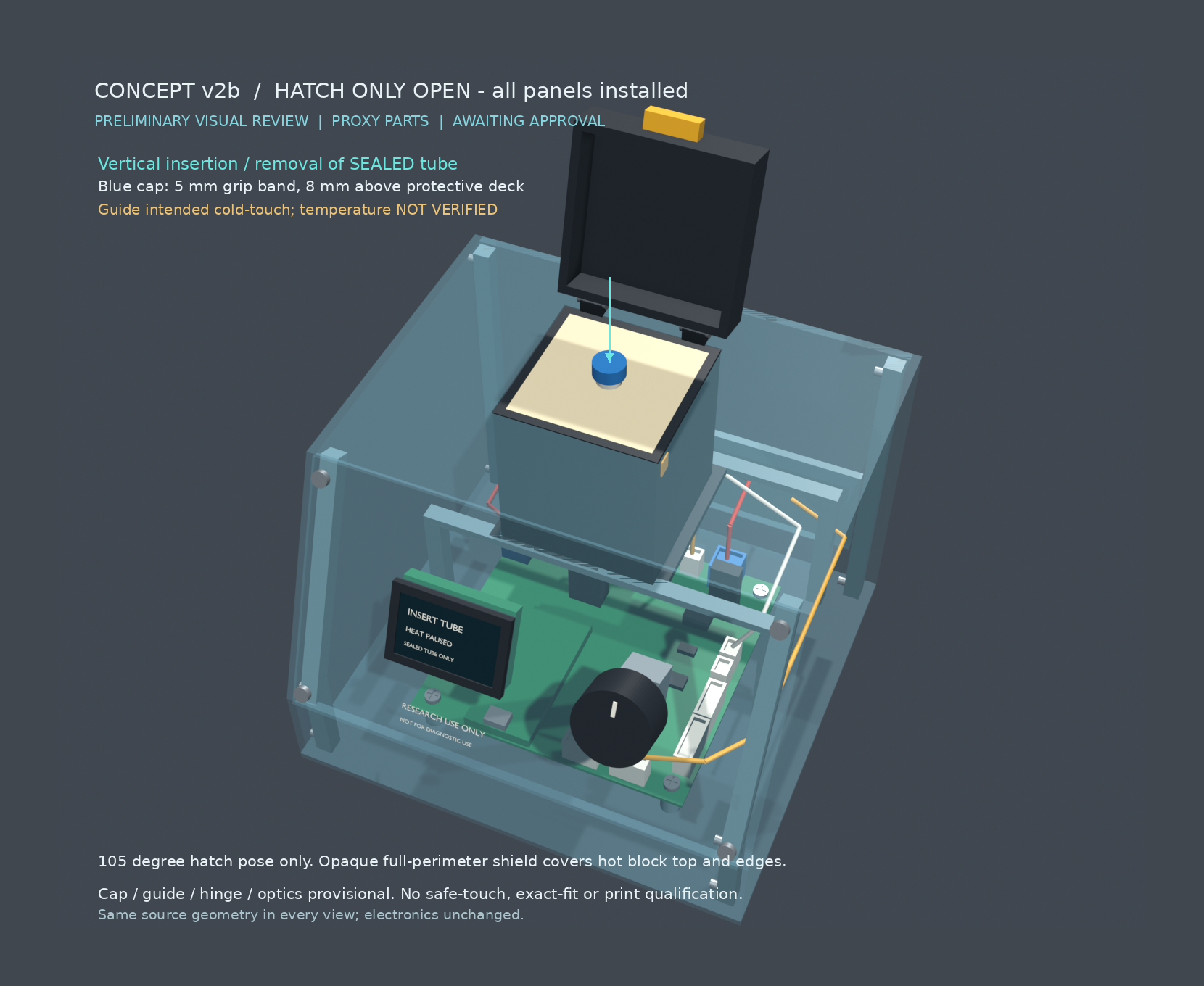
The tube body proxy now spans z85…106, retaining Ø7.5 × 21 mm as a body envelope. A distinct blue sealed-cap envelope, Ø11 × 5 mm at z106…111, provides a 5-mm-high accessible grip band, with its lower edge 3 mm above the guide and its top 8 mm above it. This cap is a selected provisional envelope, not a researched or selected PCR tube cap; combined body/cap height is 26 mm, not a claim that the earlier published 21-mm total tube fits. Actual sealed tube, cap, insertion depth and liquid location remain unresolved.
The small opaque hatch is now a hollow 59 × 59 × 15 mm hood (z103.5…118.5), with 3-mm walls/roof and an internal roof at z115.5. It clears the cap by 4.5 mm when closed. The hinge axis was raised from z104 to z108, at y55 along X, on representational pedestals, to prevent the taller hood hitting the roof at 105°. The shell's flat panels and roof stay unchanged; only the small guard hatch changes pose during normal tube access. Hinge mounting, latch and interlock are still provisional.
Cold protective guide is a design intent, not a measured property. Its insulation material, supports, heat transfer, safe-touch temperature and cap temperature require selection and thermal testing. The deck must not be assumed safe to touch merely because it is beige in the render. The independent G4A00091C cutoff and guard-interlock architecture remain required and are not replaced by this shield.
Pertinent numerical geometry checks — all millimeters
Table
Check
v2b result
Status/evidence limit
Live PCB proxy
100 × 100 × 1.29936; top z0; holes Ø3.4 at (±44,±44)
Preserved; fresh live inspection still reports 1.30-mm stackup and unchanged listed placements
Installed concept bounds
x±80; y -79.864…81; z -14.4…118.5
Native compiler: 160 × 160.864 × 132.9 overall, including protrusions
Tube body / cap
body z85…106; cap z106…111
Provisional sealed assembly envelope, not selected-part fit
0.5 nominal radial clearance; not a manufacturing tolerance
Closed cap-to-hatch roof
115.5 - 111 = 4.5
Positive geometric clearance
Guard extension beyond block XY
(49-30)/2 = 9.5 on each side
All block-top projection outside tube bore covered; computed uncovered volume0
Deck-to-block top / sleeve-to-block top
2 / 0.5 air gaps
Geometry only; no thermal adequacy claim
Hatch opening
105° about X through(-8,55,108)
5° samples from0…105: intersection volume0 with cap, tube, deck, roof and chamber
Axial sealed-tube movement
0…40 upward from installed position
1-mm samples: intersection volume0 with guide, open hatch or heater block
Reserved grip/insertion corridor
Ø26 × 40, starting z103
Intersection volume0 with open hatch and roof; provisional ergonomic envelope, not a verified hand fit
Optics proxies
z82…92; transverse optical axis z87; passage Ø3
New guard does not intersect LED/sensor proxies; deck underside8 above their tops
+Y harness overhead
underside42 - assumed connector top12 = 30
Same as v2; conditional on estimated body heights and pending real plugs
Raised chamber/gantry versus PCB
intersection volume0
Same fixed PCB; screw/tool/service qualifications remain open
The new Ø3 transverse passage in the block connects the existing optical proxy direction to the well at z87, below the protective deck; this prevents the drawing from depicting a solid block as an optical path. No actual LED/sensor geometry, dye response, field of view, tube optical window, stray-light seal or assay performance has been validated. The guard shields the top without being placed across that provisional horizontal path. Body immersion is only13 mm in the block proxy (z85…98); thermal/liquid suitability is unresolved.
Four-view meaning and labeling
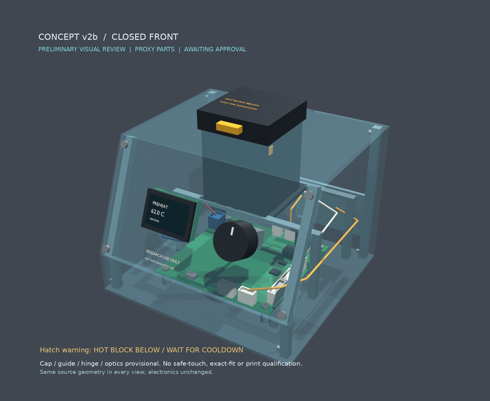
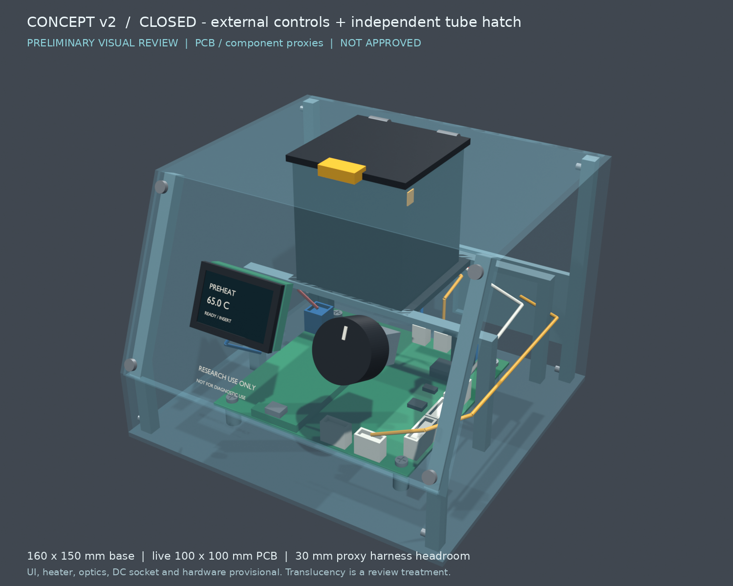
Closed front: external OLED and pushable knob remain accessible. OLED shows one coherent state: PREHEAT / 62.0 C / HEATING. Hatch carries HOT BLOCK BELOW / WAIT FOR COOLDOWN, also repeated as a readable callout. Temperatures are UI illustration, not a measurement result.
Hatch-only open: only the hatch and its grip rotate105°; roof, sides, front, rear, PCB, protective deck and tube all stay installed. The blue cap is visibly above the full guard deck. The arrow projects the actual tube axis from CAD coordinates and depicts vertical sealed-tube insertion/removal. OLED shows INSERT TUBE / HEAT PAUSED / SEALED TUBE ONLY, not simultaneous preheat and ready. No hand or exact gripper fit is implied.
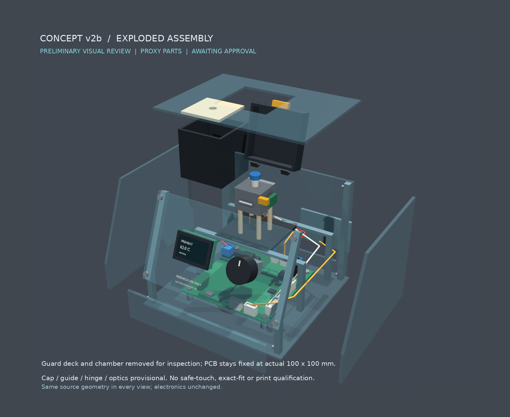
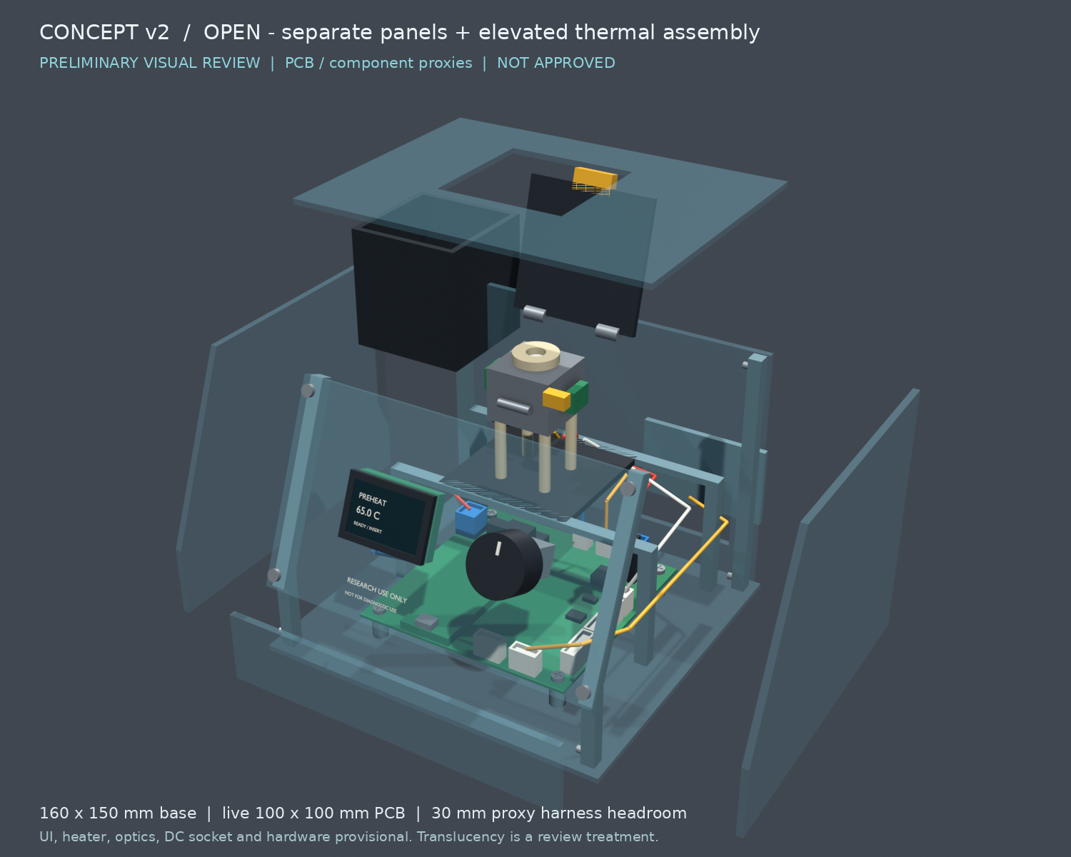
Exploded: separate deck, chamber, roof and side panels reveal the unchanged board, isolated block, cutoff and internal harness allowance. This is not the normal insertion pose. Exploded translations in mm: left(-48,0,0), right(60,0,0), roof(0,0,85), chamber(-82,48,25), guard(-82,48,45), rear service plate(0,24,0), front lower strip(0,-24,0). The tube, block, PCB and gantry remain at installed transforms; hatch alone rotates105° about its new axis.
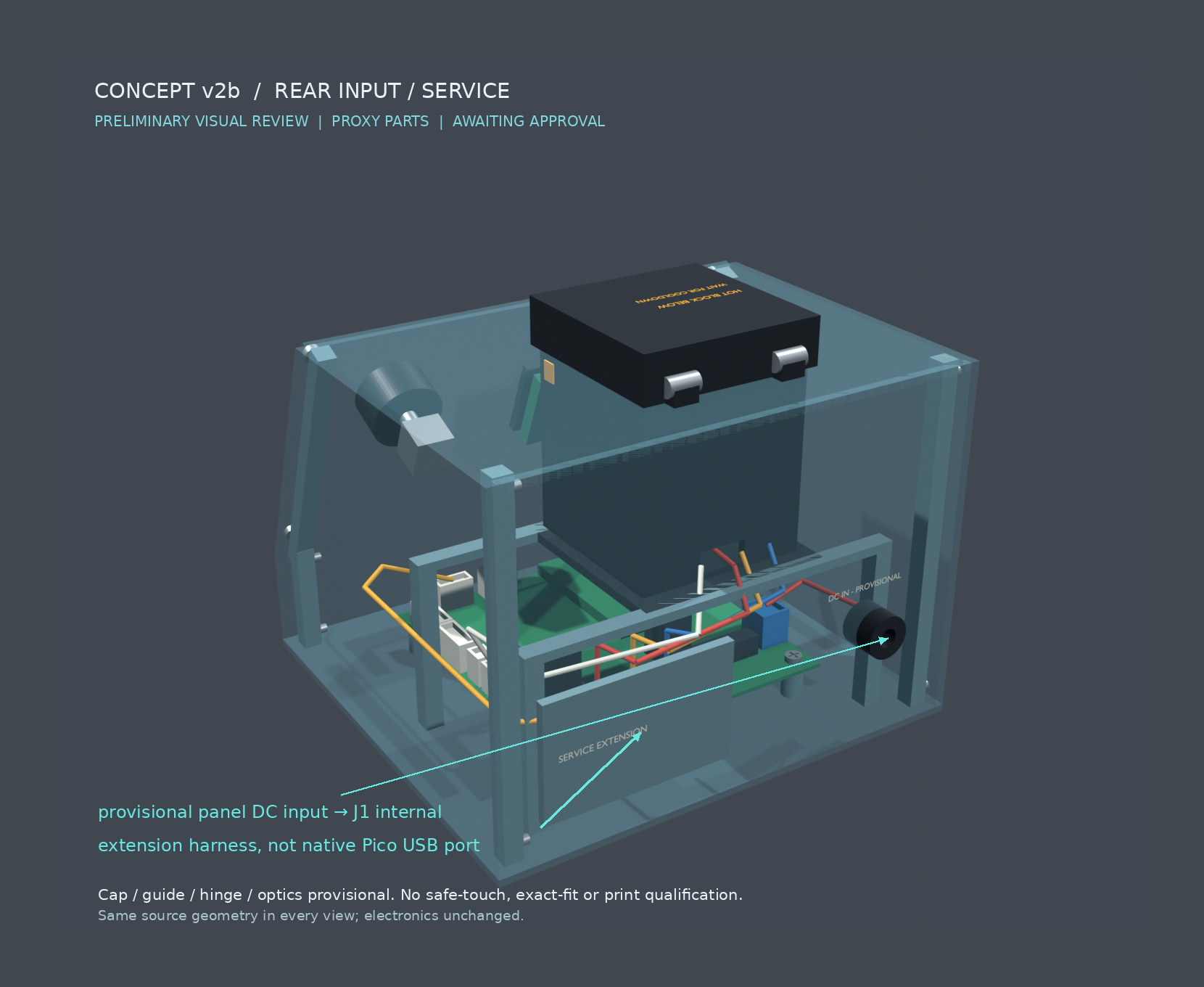
Rear: callouts explicitly read provisional panel DC input → J1 internal and extension harness, not native Pico USB port. J1 remains the real internal screw terminal. The panel socket and service extension are provisional off-board interfaces. No direct native USB aperture was added and no solder terminal is portrayed as a barrel jack.
All four views use the same updated Build123d assembly and deterministic tessellation, not image editing of v2. Perspective cameras, numeric camera positions/targets, lens52 mm, installed/presentation transforms, text placements and source scripts are preserved in the evidence asset. Render raster1500 ×1200; delivered1660 ×1360 adds80-pixel neutral margins after labeling. Final pixel means/stddev: closed78.43/22.30, hatch82.04/31.73, exploded75.88/22.44, rear76.09/20.55; no border clipping. All four previews were inspected. Translucency remains an inspection treatment, not a claim of optical-clear PETG.
Assembly and remaining scope
Use the v2 assembly sequence below, adding the full protective deck after block/optics installation and before the hooded hatch. The guide deck attaches to the chamber/insulated support concept, not directly to the hot block; final retention and materials are unresolved. Heater service still removes chamber/deck from above without removing the UI. Electronics and PCB model nodes were not mutated.
Table
Assigned v2b item
Disposition
Revise existing source for accessible sealed cap and shielded block perimeter
COMPLETED at concept level; exact parts and safe-touch behavior remain unknown
Closed front / hatch-only / exploded / rear views
COMPLETED; saved and pixel-inspected
Numeric source-bound checks and durable evidence
COMPLETED; sampled checks limited as stated
Record update, v2 superseded and v2b approval status
UNATTEMPTED intentionally; blocked by selected parts, real tolerances, thermal tests and visual approval
PCB/schematic mutation
UNATTEMPTED intentionally; preserved
Native source compilation reports114 valid solids,682 faces. Floating-solid and support findings are expected in this multi-part review assembly and are not accepted as a one-piece print. One focused geometry repair raised the hinge axis to resolve the hood/roof sweep interference; final checked samples are clear. One presentation recovery added outer margins to prevent labels triggering the renderer's border check. No third-party part fits, continuous-motion certification, certified finger protection, physical cap grip, optical performance, spill resistance or final fastening have been established. The visual revision batch is complete; overall reader engineering and v2b approval are not.
Archived concept v2 — SUPERSEDED by v2b after REVISE verdict
The following v2 record is historical. Its recessed tube, small guide, flat hatch and associated approval/check claims are superseded by v2b above; do not use it as the current safety/access reference.
Revision date: 2026-09-23. This package returns to the
original approved flat-panel visual direction, not the rejected continuous canopy. It is a complete review assembly, not fit-critical or printable manufacturing CAD. The original visual direction is approved; this geometry revision is not. Text feedback or a marked-up screenshot of either view can guide the next revision. Stop before detailed CAD until v2 is explicitly visually approved.
Live get_layout scene-tree and normalized layout_2d were inspected. Board is 100 × 100 mm at x/y ±50, with Ø3.4 NPTH at (±44,±44). Current stackup reports 1.30 mm and computed substrateThickness 1.29936 mm, superseding the earlier record's 1.21 mm. The review proxy uses 1.29936 mm, PCB top z=0 and underside z=-1.29936. Physical laminate thickness/tolerance still requires confirmation; no board was changed.
No existing PCB connector was selected for direct exterior mating with panels fitted: J1 is internal screw-terminal power, J2–J8 are internal harnesses, J9/J10 are service headers. The native run_enclosure_concept schema requires at least one designator and cannot express this empty interface set. It was therefore not called with a false J1 or fabricated interface. The previously reported J1–J10 run remains INCOMPLETE, not connector-cutout evidence. A fresh native board render succeeded but showed the PCB without usable tall connector/module bodies; proxy heights are explicitly estimated. No combined native enclosure render was claimed or needed.
The review source contains selected component envelopes rather than a full assembled-PCB replica. Connector XY envelopes come from transformed footprint polygons, not placement-origin ± half-size shortcuts; heights and other body approximations are not fit evidence. The current board has no OLED or encoder: both shown front controls are provisional off-board modules.
Testable installed geometry — millimeters
Table
Item
v2 geometry
Authority/status
Base
160 × 150; x ±80, y ±75; z -14.4 to -12
Selected concept
Complete installed bounds including knob/DC/hardware
x -80…80; y -79.864…81; z -14.4…108.5; 160 × 160.864 × 122.9 overall
Measured from compiled source
Flat walls / floor / top
3 / 2.4 / 2.4 thick
Concept dimensions, not FDM qualification
Front slope
from (y=-75,z=20) to (-40,103); 67.135° approximately from horizontal
Derived; exact atan2(83,35) in source
Roof
z 100.6…103, with 55.8-square chamber opening
Selected concept; not final fit
Chamber
55 × 55 × 58, centered x=-8,y=25; z45…103
PROVISIONAL; enlarged from earlier 45-square proxy to make space for isolation/optics
Chamber gantry
posts at x±61, y=-2 and60; crossbeam/tray underside z42
PROVISIONAL, independently supported outside PCB
+Y connector bank overhead
42-12 = 30 above tallest assumed connector
Conditional pass against 12-mm height proxy, not measured plug clearance
Chamber versus mounting screws
Chamber/tray separate from screws at ±44; some driver access requires thermal tray removal
Concept-only; tool envelope not qualified
Heater block / tube
30 × 30 × 24 at z74…98 / Ø7.5 × 21 at z79…100
Bounded provisional proxies, not exact selected parts
Block-to-chamber XY gap
9.5 per side, plus 29-mm insulating support region below block
Model dimension only; thermal adequacy NOT VERIFIED
Guard hatch
59 × 59 × 3 at z103.5…106.5; separate grip to z108.5
Ø25 × 14, x=35, front face 19 mm normal to panel center plane
PROVISIONAL off-board pushable encoder
Rear input
center x=-48,z25, rear +Y; Ø14 body / Ø6 visible bore proxy
PROVISIONAL panel-mounted DC input wired internally to J1; not J1 itself
Rear service plate
61 × 38 covering 55 × 32 opening, center x37
Reserved extension-harness access, not a native USB-aligned cutout
The base matches the allowed expanded footprint; the full installed height is 122.9 mm including the bottom plate and guard grip. This is a selected visual proportion, not a frozen product envelope. Source measurements, not rendered pixels, control these values.
Access, wiring and safety intent
Closed view exposes the OLED face and knob. The knob back starts 5 mm normal to the panel center plane versus the panel face at 1.5 mm, leaving 3.5 mm nominal back clearance; a 1-mm provisional push remains geometrically clear of the panel. Actual encoder travel, grip ergonomics, mounting and wiring are unqualified.
Only the small opaque hatch opens for tube insertion; no translucent panel is removed. A 105° opening pose is shown. The yellow latch and guard switch are symbolic geometry, not a qualified retention/interlock mechanism. A final light-tight overlap and hinge mount remain unresolved.
Empty-block preheat, guarded hot insertion with heater paused, liquid equilibration before assay timing, sealed-tube handling and cooldown remain required. The G4A00091C independent one-shot cutoff remains mandatory and is represented separately at the block; its mounting/contact and lead geometry are provisional.
Gantry posts are outside the PCB outline; overhead tray leaves 30 mm above the 12-mm assumed +Y connector envelope. Real mated plugs, bend radii, fingers and insertion paths must be checked later. Harness cylinders are route-intent proxies, not completed pin-level wiring or strain relief.
Rear DC input is a new provisional panel-mounted input connected to the existing internal J1 screw terminal. Exact socket, adapter plug, polarity, strain relief and cable bend are unresolved.
J2 heater, J3 cutoff, J4 guard, J5 NTC, J6 thermocouple, J7 optical sensor and J8 illumination remain internal. J9/J10 reach a reserved rear service extension path along x≈68; this requires a future selected harness. Direct Pico service is available in the concept by removing the lower front service strip. Live U1 origin is (-18,-22.476), rotated180°; its USB shield/test-pad region lies near y=-46.5. This is not a verified mating face or height, so no USB-sized external cutout was authored.
Separate printed translucent PETG sheets, visible rails and representational screws establish assembly intent. Blender transparency is an inspection treatment, not a promise of optically clear FDM PETG. No molded continuous canopy is used.
Assembly / service sequence
Lay down the separate bottom panel; install rails and provisional PCB supports.
Lower PCB onto the four existing-hole supports and install representative M3 retention screws. No new PCB holes or placement changes.
Fit independent gantry posts/crossbeams; attach internal harnesses while overhead chamber tray is absent.
Install the isolated block/optics/cutoff and spill tray as a removable module. Fit the chamber wall cassette and guard system.
Fit front UI sheet with off-board display/encoder and a service loop; connect panel DC input and service extension harness.
Fit separately removable side, rear and roof sheets. Routine tube insertion uses only the hatch. Heater service removes roof/chamber module without removing the UI; PCB removal reverses the overhead-module steps.
Fasteners are separate representational solids: four PCB M3-style screws, eight side-rail screw proxies and four front UI screws. Threads, hole pilots, captive nuts/inserts, rail attachment, full panel fastener count, support span and underside solder clearance are intentionally not final. The bottom panel is separate but is not displaced in the open render. The review Compound is one asset containing independently named solids; no mechanical model nodes were attached to or substituted into the live PCB.
Cameras and presentation transforms
Both views use the same Build123d solids tessellated to Blender; no generated image reconstruction. All source geometry is in true mm; render meshes are scaled once to meters. Installed transforms remain unchanged in source.
Perspective lens52 mm, 1500 × 1200 pixels. Closed camera (212.394,-349.883,276.436), target(0,0.568,47.050). Open camera(290.793,-468.408,389.376), target(6,1.5,81.8).
Open-only translations: left panel(-48,0,0), right panel(60,0,0), roof(0,0,75), chamber wall cassette(-82,48,25), rear service cover(0,24,0), lower front strip(0,-24,0). Hatch rotates -105° about +X through(-8,55,104). PCB, heater/block and gantry stay installed.
One geometry correction lowered roof below the hatch edge. One presentation correction widened the closed camera framing. Final inspected pixels: closed mean81.89/std24.94; open mean77.34/std22.84; edge-cutoff false for both. No ground plane, blown-out white shell, or cropped assembly.
Verification / scope disposition
Table
Assigned item
Status
Evidence or limit
Live board/hole/connector inspection
COMPLETED
Normalized geometry plus scene tree; final read-only summary still82 components,52 nets,100 ×100 board
Preliminary Build123d whole review assembly
COMPLETED
Native asset compilation:111 solids,655 faces; all111 locally valid; PCB bounds/holes match live frame
Closed exposed controls and independent hatch
COMPLETED for visual review
Inspected rendered pixels; no panel covering control faces; sampled hatch/roof collision volume0 at5° increments from0 to105°
Open/exploded same-source assembly
COMPLETED
Named removable panels, visible actual-scale PCB proxy, raised chamber, isolation and harness space
Geometry checks
COMPLETED within concept scope
Gantry/tray/chamber versus PCB intersection volume0; 30-mm conditional connector overhead; not a complete collision/ergonomic study
Durable assets and concept record
COMPLETED
Source, both PNGs and reproducibility evidence linked above
Native automatic connector-cutout concept
UNATTEMPTED / not applicable
Tool requires ≥1 exterior PCB interface; none selected; earlier incomplete J1–J10 result not reused
Exact UI/heater/socket/tube/optics fit, print qualification and detailed CAD
UNATTEMPTED intentionally
Exact parts, tolerances, process profile and visual approval remain open
PCB/schematic mutation
UNATTEMPTED intentionally
Assets and this record only; electronics preserved
Warnings, not release claims: Actual connector/body heights, tube-cap dimensions, mated harness volumes, plug paths, PCB underside landings, additional support needs, heater retention/thermal isolation, spill protection, optical darkness, hot-surface guarding, interlock behavior, fastener engagement and printing are NOT VERIFIED. The asset compiler's floating-solid and downward-face findings are expected for a multi-part installed review assembly; they are not evidence it can be printed as one object. Ordinary PETG FDM is the intended prototype process, with flat sheets printed broad-face down, but nozzle, layer height, build volume, supports and calibration are deliberately not qualified. No manufacturing export or order was produced.
Batch completion means the visual concept package is complete. Overall reader/enclosure engineering is not complete and v2 is not approved.
Archived v1 — REJECTED continuous-canopy geometry
The following historical v1 text is retained for traceability only. Its canopy arrangement, approval questions and thickness/envelope statements are superseded by v2 above; it is not an approved mechanical reference.
Status
Concept revision: v1 — awaiting visual approval. This is geometry-bound preliminary massing, not printable release CAD.
The native enclosure-concept inspection could resolve the board outline and connectors but found no usable component 3D bodies. The review assembly therefore uses a deterministic PCB proxy based on the live 100 × 100 mm outline, four measured mounting holes, and connector footprint envelopes. The PCB is not recentered or resized.
Transparent/translucent PETG outer shell so electronics and wiring remain visible.
Separate opaque black PETG optical/tube chamber at the rear.
Sloped front interface with a provisional 0.96-inch OLED envelope on the left and pushable encoder on the right.
Current 100 × 100 mm PCB mounted horizontally using its four 3.4 mm mounting holes at (±44, ±44) mm.
J3–J10 are treated as internal/service harness connections. The final shell will expose only the certified 12 V power input and required programming/service access.
Heater block is aluminum, isolated from printed plastic by insulation and an air gap. The printed chamber is not credited as heater fault protection.
Concept envelope
Table
Item
Concept v1 value
Status
Outer width
148 mm
Selected concept value
Outer depth
138 mm
Selected concept value
Overall geometry height
92.01 mm
Derived from model bounds
Ordinary wall
3.0 mm
Fixed enclosure rule
Floor
2.4 mm
Fixed enclosure rule
Main PCB
100 × 100 × 1.21 mm
Measured from live project
PCB standoff region
10 mm
Provisional; detailed boss geometry deferred
Optical chamber
45 × 45 × 58 mm
Provisional replaceable-module envelope
Aluminum block proxy
30 × 30 × 24 mm
Provisional thermal-mass envelope
PCR tube proxy
Ø7.5 × 21 mm
Conservative published 0.2 mL tube envelope
OLED module proxy
30–34 mm class
Provisional; exact module not selected
Encoder
EC11-class, Ø6 mm shaft
Provisional; exact MPN not selected
Published tube references used for bounded massing: SPL 0.2 mL tubes specify 7.26 mm diameter and 20.80 mm height; BRAND flat-cap tubes specify 7.5 mm diameter and 20.8 mm height. The model uses Ø7.5 × 21 mm. Published 0.96-inch SSD1306 module examples are approximately 27.3 × 27.3 × 2.37 mm to 30 × 30 mm. EC11-class encoders use a nominal Ø6 mm shaft and an approximately 11–12 mm body class.
Recommended chamber material: black PETG; ASA is acceptable if the printer is enclosed and tuned.
Provisional nozzle: 0.4 mm.
Provisional layer height: 0.20 mm.
Minimum expected printer volume: 220 × 220 × 250 mm.
Base prints open-side up. Lid/canopy prints with its broad exterior face on the bed when detailed geometry permits.
Detailed fits, screw bosses, heat-set inserts, hinge, guard switch mount, cable strain relief, and optical apertures are deferred until concept approval and exact part selection.
Safety and thermal conditions
The independent G4A00091C one-shot thermal cutoff remains mandatory.
The tube is inserted through a guarded, light-tight workflow after empty-block preheat.
Assay timing starts after liquid equilibration, not at tube insertion.
Printed PETG must not directly support or contact the hottest heater surfaces.
No thermal adequacy, optical darkness, spill resistance, snap life, or ingress rating is claimed at concept stage.
The open view shows the provisional OLED/encoder panel, the current PCB proxy, the opaque chamber, aluminum block proxy, tube proxy, and separated canopy. The transparent shell rendering is illustrative of translucent PETG; actual optical clarity depends on material, wall orientation, layer height, and finishing.
Approval questions
Visual approval is required before detailed CAD. Review:
Overall footprint and height.
Sloped front UI arrangement.
Rear-right opaque chamber position and size.
Transparent canopy and seam proportions.
Whether the complete upper canopy should lift off, hinge, or be split into a fixed electronics cover plus a smaller service lid.
Text feedback or a marked-up screenshot of either rendered view can be used for revision v2.
# Enclosure Concept Design Record
## Concept v2c — removable whole rear panel, VISUALLY APPROVED
### Detailed-CAD input confirmed after approval
On 2026-09-23 the user agreed to the recommended FDM profile: translucent PETG for the visible panels, black PETG for the opaque guarded chamber, 0.4 mm nozzle. Nominal 0.20 mm layer height is a provisional starting point; printer/build volume and fit calibration are unknown, so test coupons and build-volume verification are still required. Refine v2c geometry, not a new silhouette. Do not claim the heater/tube/optics/OLED/encoder/power-inlet interfaces fit a real product until selected parts and drawings or measurements exist.
Revision date: 2026-09-23. **v2c supersedes v2b and v2.** Adopted requirement: unscrew the whole rear panel for infrequent service/programming rather than adding a service extension. v2c directly edits the existing v2b Build123d source, not PNG-derived geometry. The original flat screw-joined translucent-panel styling, opaque guarded chamber, front controls and live 100 × 100 mm PCB are preserved. On 2026-09-23 the user explicitly replied "yes, looks good" to the v2c view/approval request; v2c is now the approved visual reference for subsequent detailed design. This approval covers appearance and access intent only, not exact fit, safe-touch behavior, manufacturability, or a printable release.
### Current durable assets
- [Build123d source — reader-concept-v2c.build123d](https://cdn.flux.ai/document_assets/reader-concept-v2c-d2986ecd-6574-4b05-91ab-a95fd50c8718.build123d)
- [Closed front](https://cdn.flux.ai/document_assets/reader-concept-v2c-closed-front-69ed89ac-0df2-4b42-8783-4d7b1e58b358.png)
- [Hatch-only open — every shell panel installed](https://cdn.flux.ai/document_assets/reader-concept-v2c-hatch-open-3060353f-90a8-42fc-88ee-419f487daa47.png)
- [Exploded assembly — entire rear panel removable](https://cdn.flux.ai/document_assets/reader-concept-v2c-exploded-afdea153-3295-4f38-aee5-d6957961c9a0.png)
- [Rear installed](https://cdn.flux.ai/document_assets/reader-concept-v2c-rear-installed-5e968986-607a-4045-85bf-1767313da7c4.png)
- [Rear service-open](https://cdn.flux.ai/document_assets/reader-concept-v2c-rear-service-open-5f3a994c-523d-4768-9923-ccf460da86a6.png)
- [Rear installed/service-open comparison](https://cdn.flux.ai/document_assets/reader-concept-v2c-rear-comparison-9e8f16ae-fb72-4e5d-8707-40aecaf71972.png)
- [Numeric checks, poses, cameras and reproducibility evidence](https://cdn.flux.ai/document_assets/reader-concept-v2c-review-evidence-908663e9-7f02-446e-926f-5d78da655aff.json)
### What changed and what remains installed
Removed the rear service extension harness, separate service plate, dedicated 55 × 32 mm service aperture and their labels. The whole 154 × 3 × 112.1 mm rear panel is removable; six representational screw heads face rearward (+Y), at x±73, z−5/44/93, with head centers y76. The panel top is z100.1, nominally 0.5 below the roof underside z100.6, to allow normal withdrawal. These dimensions demonstrate intent, not final thread engagement, fastening, tolerance or tool qualification.
The separate provisional panel-mounted 12 V DC inlet remains at (−48,75,25), wired to **J1 internal**, not substituted for J1 or presented as the Pico USB connector. A provisional two-pole inline disconnect and paired slack pigtail allow the inlet to travel with the panel. The fixed half is centered (−56,61,25); the panel half is (−56,67,25). The approximately 56.13 mm segmented pigtail centerline illustrates slack only, not a usable withdrawal-distance or bend-radius guarantee.
Concept service sequence: unplug the external adapter, allow full cooldown, remove the six rear-facing screws, withdraw the panel cautiously only as the real harness permits, disconnect the internal DC coupler, then remove the whole panel without pulling on J1. The service-open pose assumes the coupler is already unplugged. The panel, inlet, loose pigtail and unplugged half are translated (110,85,0); the screws are translated (110,110,0). Roof, sides, front controls, PCB and small tube hatch remain installed in this service view. Actual connector selection, polarization, retention, strain relief and safe slack length remain open.
Normal tube access is independent: hatch-only open rotates the small opaque hood 105° and changes no panel position. The v2b protective deck, raised sealed cap, optical passage proxies, hot-block warning and coherent OLED states are retained. The exploded view separates the whole rear panel rather than a small cover; it is an assembly illustration, not the normal service or insertion pose.
### Source-bound numerical checks — millimeters
| Check | v2c result | Meaning and limit |
|---|---|---|
| Live board and holes | 100 × 100 × 1.29936; top z0; Ø3.4 at (±44,±44) | Unchanged deterministic proxy tied to live layout; no PCB/schematic mutations |
| Installed bounds | x±80; y−79.864…81; z−14.4…118.5 | Overall 160 × 160.864 × 132.9, including protrusions; base160 ×150 |
| Native source compilation | 132 solids, 831 faces; locally all solids valid | Multi-part visual review assembly, not a one-piece print |
| Legacy service extension/plate | No matching solids remain | Names and source geometry checked; old labels removed from current views |
| Former service aperture | 5280 mm³ material, equal to55 ×32 ×3 | Former aperture fully filled; only DC inlet and representational screw holes remain |
| Rear-facing screwdriver approaches | Six Ø10 ×40 cylinders, +Y from y77 | No intersection with other modeled solids; not selected-driver or hand clearance |
| Panel normal withdrawal | +Y0…35, every5 | No checked interference with static geometry |
| Disconnected full rear assembly withdrawal | +Y0…85 every5, then +X10…110 every10 at y85 | Zero checked interference for panel, inlet, pigtail and unplugged half; wire flexibility not simulated |
| Concept approach above U1 | Ø10 path at z25; length130.44 | No interference against selected proxies; ends above circuitry, not at a mating face |
| Concept approach above J9 / J10 | Ø10 paths at z25; lengths170.53 /187.46 | Same limited long-tool/inspection check; not finger reach or cable insertion |
| Rear inner face to approximate USB region | y72 to approximately y−46:118 depth | Emphasizes reach uncertainty; USB region is not a verified port datum |
| Cap grip / cap-to-closed-hood clearance | 5 /4.5 | Preserved v2b geometry; cap top8 above guide |
| Hatch and axial tube samples | 105° hatch;40 axial travel | Rerun checked samples show zero interference; not continuous motion or actual part-fit qualification |
| Conditional +Y harness headroom | underside42 − assumed connector12 =30 | Unchanged; mated plugs, actual body heights and harness bends unresolved |
The access centerlines enter near (−37,80,25), run to (−37,−30,25), then toward volumes **above** U1 or J9/J10. J9/J10 modeled body centers are (12.75,−45.525) and (29.75,−45.525); U1 live placement origin is approximately (−18,−22.476). These checks establish a plausible long-tool/inspection volume beneath the chamber in this sparse proxy assembly, **not that removing the rear panel exposes the native USB jack, that the jack is directly reachable, or that a USB cable can mate**. The dashed render annotation is a hypothetical hidden path, not a visible connector or extension harness. Actual U1 USB face/axis, plug overmold, fully populated-board obstacles, fingers and cable manipulation remain unverified; another panel may ultimately require removal.
### Evidence, assumptions and scope disposition
All five views tessellate the same v2c Build123d assembly; the comparison combines the two rear views. Evidence includes render/tessellation/annotation/validation scripts, cameras, presentation transforms and numerical results. Views are separately framed, not a scale-comparison drawing. Single views1660 ×1360; rear comparison3320 ×1360. Final luminance mean/std: closed78.27/21.96, hatch81.80/31.20, exploded75.10/20.68, rear installed77.09/22.34, rear service-open73.82/18.63, comparison75.45/20.63; no detected border clipping. Every view was visually inspected, including the service-open view separately. Durable image/evidence assets were read back after saving; native source compilation also succeeded.
| Assigned v2c item | Disposition |
|---|---|
| Continue v2b source; remove service extension, plate, aperture and labels | COMPLETED |
| Whole removable rear panel with outward-facing screw positions | COMPLETED at concept level; sampled approach/removal checks clear |
| Separate provisional panel DC inlet with disconnect/slack provision | COMPLETED as visual geometry; selected-part wiring/retention qualification UNATTEMPTED |
| Preserve PCB, front controls, flat panels, opaque guard and independent hatch | COMPLETED; electronics and layout left unchanged |
| Closed, hatch-only, exploded, rear installed/service-open views and comparison | COMPLETED; saved and inspected |
| Reasonable concept approach volume toward service circuitry | COMPLETED only for stated proxy cylinders ending above circuitry |
| Actual native USB reach and cable mating | UNATTEMPTED / unresolved; blocked by missing true port, plug and populated-assembly geometry |
| Record, supersession, asset links and evidence | COMPLETED |
| Detailed printable CAD, final fastening, FDM, thermal/safe-touch and optical qualification | UNATTEMPTED intentionally; beyond visual approval checkpoint |
No unresolved tool failure blocks the delivered artifacts. The Files editor could not be opened because the requester frontend session was unavailable; assets and this record were saved independently. Native compiler floating-solid/support findings are noteworthy for a multi-part installed assembly and do not imply printable readiness. No electronics, net, PCB placement, board outline, stackup or layout-model nodes were changed. **v2c was explicitly visually approved on 2026-09-23; overall enclosure/service engineering is not complete.**
## Archived concept v2b — SUPERSEDED by v2c
The following v2b section is historical. Its rear service extension, small service plate/aperture and approval request are superseded by v2c above. Its protected-cap concept is retained, subject to the same unverified fit and thermal limitations.
Revision date: 2026-09-23. **v2 is superseded following the independent review verdict REVISE.** v2b edits the existing v2 Build123d source; it was not reconstructed from PNGs. The approved flat screw-joined translucent-panel visual direction, live PCB frame and electronics are retained. This is preliminary visual geometry only, not detailed printable CAD, a safe-touch qualification or a thermal-performance claim. Text feedback or a marked-up screenshot may be used for the next revision; explicit v2b visual approval is required before detailed CAD.
### v2b durable source and four views
- [Build123d source — concept v2b](https://cdn.flux.ai/document_assets/reader-concept-v2b-c25033fd-a1a8-4abf-a568-7ce95c3b3dbf.build123d)
- [Closed front](https://cdn.flux.ai/document_assets/reader-concept-v2b-closed-front-a0d088db-a6a6-4853-80ef-9eb5faf7a2d9.png)
- [Hatch-only open, all panels installed](https://cdn.flux.ai/document_assets/reader-concept-v2b-hatch-open-93a09294-454c-4e4d-8a2d-1aa8db34f314.png)
- [Exploded assembly](https://cdn.flux.ai/document_assets/reader-concept-v2b-exploded-78f8bac3-464c-48c4-91eb-8f5c20be3590.png)
- [Rear input/service](https://cdn.flux.ai/document_assets/reader-concept-v2b-rear-bfaf2646-94ba-45ae-bc85-55392ebe1c23.png)
- [Numeric geometry checks, cameras, poses, pixel checks and reproducible rendering source](https://cdn.flux.ai/document_assets/reader-concept-v2b-review-evidence-6f307445-520a-4963-be71-0fe5685378fd.json)
### Corrected protected insertion concept
The v2 problem was real: its tube ended below the small guide, and the block perimeter was not fully guarded. v2b replaces that small guide with a **49 × 49 mm protective deck**, covering the 30 × 30 mm hot block top and edges inside the opaque chamber, with only an Ø8.5 mm tube passage. A narrow central sleeve extends down to z98.5; the deck spans z100…103, above the block top z98. The existing chamber walls guard the block sides. This is geometric shielding, not a certified finger probe or spill test.
The tube body proxy now spans z85…106, retaining Ø7.5 × 21 mm as a body envelope. A distinct blue sealed-cap envelope, **Ø11 × 5 mm at z106…111**, provides a 5-mm-high accessible grip band, with its lower edge 3 mm above the guide and its top 8 mm above it. This cap is a **selected provisional envelope**, not a researched or selected PCR tube cap; combined body/cap height is 26 mm, not a claim that the earlier published 21-mm total tube fits. Actual sealed tube, cap, insertion depth and liquid location remain unresolved.
The small opaque hatch is now a hollow 59 × 59 × 15 mm hood (z103.5…118.5), with 3-mm walls/roof and an internal roof at z115.5. It clears the cap by 4.5 mm when closed. The hinge axis was raised from z104 to **z108**, at y55 along X, on representational pedestals, to prevent the taller hood hitting the roof at 105°. The shell's flat panels and roof stay unchanged; only the small guard hatch changes pose during normal tube access. Hinge mounting, latch and interlock are still provisional.
**Cold protective guide is a design intent, not a measured property.** Its insulation material, supports, heat transfer, safe-touch temperature and cap temperature require selection and thermal testing. The deck must not be assumed safe to touch merely because it is beige in the render. The independent G4A00091C cutoff and guard-interlock architecture remain required and are not replaced by this shield.
### Pertinent numerical geometry checks — all millimeters
| Check | v2b result | Status/evidence limit |
|---|---:|---|
| Live PCB proxy | 100 × 100 × 1.29936; top z0; holes Ø3.4 at (±44,±44) | Preserved; fresh live inspection still reports 1.30-mm stackup and unchanged listed placements |
| Installed concept bounds | x±80; y -79.864…81; z -14.4…118.5 | Native compiler: 160 × 160.864 × 132.9 overall, including protrusions |
| Tube body / cap | body z85…106; cap z106…111 | Provisional sealed assembly envelope, not selected-part fit |
| Cap grip band | 5 high; lower edge 3 above guide; top 8 above guide | Geometrically exposed in hatch-only view |
| Guide bore / body | Ø8.5 / Ø7.5 | 0.5 nominal radial clearance; not a manufacturing tolerance |
| Closed cap-to-hatch roof | 115.5 - 111 = 4.5 | Positive geometric clearance |
| Guard extension beyond block XY | (49-30)/2 = 9.5 on each side | All block-top projection outside tube bore covered; computed uncovered volume0 |
| Deck-to-block top / sleeve-to-block top | 2 / 0.5 air gaps | Geometry only; no thermal adequacy claim |
| Hatch opening | 105° about X through(-8,55,108) | 5° samples from0…105: intersection volume0 with cap, tube, deck, roof and chamber |
| Axial sealed-tube movement | 0…40 upward from installed position | 1-mm samples: intersection volume0 with guide, open hatch or heater block |
| Reserved grip/insertion corridor | Ø26 × 40, starting z103 | Intersection volume0 with open hatch and roof; provisional ergonomic envelope, not a verified hand fit |
| Optics proxies | z82…92; transverse optical axis z87; passage Ø3 | New guard does not intersect LED/sensor proxies; deck underside8 above their tops |
| +Y harness overhead | underside42 - assumed connector top12 = 30 | Same as v2; conditional on estimated body heights and pending real plugs |
| Raised chamber/gantry versus PCB | intersection volume0 | Same fixed PCB; screw/tool/service qualifications remain open |
The new Ø3 transverse passage in the block connects the existing optical proxy direction to the well at z87, below the protective deck; this prevents the drawing from depicting a solid block as an optical path. **No actual LED/sensor geometry, dye response, field of view, tube optical window, stray-light seal or assay performance has been validated.** The guard shields the top without being placed across that provisional horizontal path. Body immersion is only13 mm in the block proxy (z85…98); thermal/liquid suitability is unresolved.
### Four-view meaning and labeling
1. **Closed front:** external OLED and pushable knob remain accessible. OLED shows one coherent state: `PREHEAT / 62.0 C / HEATING`. Hatch carries `HOT BLOCK BELOW / WAIT FOR COOLDOWN`, also repeated as a readable callout. Temperatures are UI illustration, not a measurement result.
2. **Hatch-only open:** only the hatch and its grip rotate105°; roof, sides, front, rear, PCB, protective deck and tube all stay installed. The blue cap is visibly above the full guard deck. The arrow projects the actual tube axis from CAD coordinates and depicts vertical sealed-tube insertion/removal. OLED shows `INSERT TUBE / HEAT PAUSED / SEALED TUBE ONLY`, not simultaneous preheat and ready. No hand or exact gripper fit is implied.
3. **Exploded:** separate deck, chamber, roof and side panels reveal the unchanged board, isolated block, cutoff and internal harness allowance. This is not the normal insertion pose. Exploded translations in mm: left(-48,0,0), right(60,0,0), roof(0,0,85), chamber(-82,48,25), guard(-82,48,45), rear service plate(0,24,0), front lower strip(0,-24,0). The tube, block, PCB and gantry remain at installed transforms; hatch alone rotates105° about its new axis.
4. **Rear:** callouts explicitly read `provisional panel DC input → J1 internal` and `extension harness, not native Pico USB port`. J1 remains the real internal screw terminal. The panel socket and service extension are provisional off-board interfaces. No direct native USB aperture was added and no solder terminal is portrayed as a barrel jack.
All four views use the same updated Build123d assembly and deterministic tessellation, not image editing of v2. Perspective cameras, numeric camera positions/targets, lens52 mm, installed/presentation transforms, text placements and source scripts are preserved in the evidence asset. Render raster1500 ×1200; delivered1660 ×1360 adds80-pixel neutral margins after labeling. Final pixel means/stddev: closed78.43/22.30, hatch82.04/31.73, exploded75.88/22.44, rear76.09/20.55; no border clipping. All four previews were inspected. Translucency remains an inspection treatment, not a claim of optical-clear PETG.
### Assembly and remaining scope
Use the v2 assembly sequence below, adding the full protective deck after block/optics installation and before the hooded hatch. The guide deck attaches to the chamber/insulated support concept, not directly to the hot block; final retention and materials are unresolved. Heater service still removes chamber/deck from above without removing the UI. Electronics and PCB model nodes were not mutated.
| Assigned v2b item | Disposition |
|---|---|
| Revise existing source for accessible sealed cap and shielded block perimeter | COMPLETED at concept level; exact parts and safe-touch behavior remain unknown |
| Closed front / hatch-only / exploded / rear views | COMPLETED; saved and pixel-inspected |
| Numeric source-bound checks and durable evidence | COMPLETED; sampled checks limited as stated |
| Record update, v2 superseded and v2b approval status | COMPLETED |
| Detailed printable CAD / FDM qualification / thermal qualification | UNATTEMPTED intentionally; blocked by selected parts, real tolerances, thermal tests and visual approval |
| PCB/schematic mutation | UNATTEMPTED intentionally; preserved |
Native source compilation reports114 valid solids,682 faces. Floating-solid and support findings are expected in this multi-part **review** assembly and are not accepted as a one-piece print. One focused geometry repair raised the hinge axis to resolve the hood/roof sweep interference; final checked samples are clear. One presentation recovery added outer margins to prevent labels triggering the renderer's border check. No third-party part fits, continuous-motion certification, certified finger protection, physical cap grip, optical performance, spill resistance or final fastening have been established. The visual revision batch is complete; overall reader engineering and v2b approval are not.
## Archived concept v2 — SUPERSEDED by v2b after REVISE verdict
The following v2 record is historical. Its recessed tube, small guide, flat hatch and associated approval/check claims are superseded by v2b above; do not use it as the current safety/access reference.
Revision date: 2026-09-23. This package returns to the [original approved flat-panel visual direction](https://cdn.flux.ai/document_assets/rt-lamp-transparent-learning-concept-v1-2414ac45-82bc-4ea3-83f1-3f29331e9967.png), not the rejected continuous canopy. It is a complete review assembly, not fit-critical or printable manufacturing CAD. The original visual direction is approved; **this geometry revision is not**. Text feedback or a marked-up screenshot of either view can guide the next revision. Stop before detailed CAD until v2 is explicitly visually approved.
### Saved review package
- [Build123d source / separate-solid review assembly](https://cdn.flux.ai/document_assets/reader-concept-v2-ff62f34a-04af-4759-8f20-dbdbc11de538.build123d)
- [Closed exterior perspective](https://cdn.flux.ai/document_assets/reader-concept-v2-closed-1ad091fe-3903-436e-84bd-1f032ef02a72.png)
- [Opened/exploded perspective](https://cdn.flux.ai/document_assets/reader-concept-v2-open-82a40416-36a2-4267-85bb-ca93d3b86bc4.png)
- [Cameras, transforms, geometry checks and Blender/tessellation source](https://cdn.flux.ai/document_assets/reader-concept-v2-review-evidence-71329723-c1dc-4f1d-84b6-6a4761343588.json)
### Geometry authority and native-tool limitation
Live `get_layout` scene-tree and normalized `layout_2d` were inspected. Board is 100 × 100 mm at x/y ±50, with Ø3.4 NPTH at (±44,±44). **Current stackup reports 1.30 mm and computed substrateThickness 1.29936 mm**, superseding the earlier record's 1.21 mm. The review proxy uses 1.29936 mm, PCB top z=0 and underside z=-1.29936. Physical laminate thickness/tolerance still requires confirmation; no board was changed.
No existing PCB connector was selected for direct exterior mating with panels fitted: J1 is internal screw-terminal power, J2–J8 are internal harnesses, J9/J10 are service headers. The native `run_enclosure_concept` schema requires at least one designator and cannot express this empty interface set. It was therefore not called with a false J1 or fabricated interface. The previously reported J1–J10 run remains INCOMPLETE, not connector-cutout evidence. A fresh native board render succeeded but showed the PCB without usable tall connector/module bodies; proxy heights are explicitly estimated. No combined native enclosure render was claimed or needed.
[Native PCB reference, inspected before proxy construction](https://assetpipeline.flux.ai/?key=document_assets%2Fsingle-tube-rt-lamp-reader-2e5d54cead22612065569f6d27992938.glb&format=webp&view=iso&size=1024x1024&cadMode=true&yaw=315&pitch=40&up=z&zoom=1&ortho=true&bg=transparent)
The review source contains selected component envelopes rather than a full assembled-PCB replica. Connector XY envelopes come from transformed footprint polygons, not placement-origin ± half-size shortcuts; heights and other body approximations are not fit evidence. The current board has no OLED or encoder: both shown front controls are provisional off-board modules.
### Testable installed geometry — millimeters
| Item | v2 geometry | Authority/status |
|---|---|---|
| Base | 160 × 150; x ±80, y ±75; z -14.4 to -12 | Selected concept |
| Complete installed bounds including knob/DC/hardware | x -80…80; y -79.864…81; z -14.4…108.5; 160 × 160.864 × 122.9 overall | Measured from compiled source |
| Flat walls / floor / top | 3 / 2.4 / 2.4 thick | Concept dimensions, not FDM qualification |
| Front slope | from (y=-75,z=20) to (-40,103); 67.135° approximately from horizontal | Derived; exact atan2(83,35) in source |
| Roof | z 100.6…103, with 55.8-square chamber opening | Selected concept; not final fit |
| Chamber | 55 × 55 × 58, centered x=-8,y=25; z45…103 | PROVISIONAL; enlarged from earlier 45-square proxy to make space for isolation/optics |
| Chamber gantry | posts at x±61, y=-2 and60; crossbeam/tray underside z42 | PROVISIONAL, independently supported outside PCB |
| +Y connector bank overhead | 42-12 = 30 above tallest assumed connector | Conditional pass against 12-mm height proxy, not measured plug clearance |
| Chamber versus mounting screws | Chamber/tray separate from screws at ±44; some driver access requires thermal tray removal | Concept-only; tool envelope not qualified |
| Heater block / tube | 30 × 30 × 24 at z74…98 / Ø7.5 × 21 at z79…100 | Bounded provisional proxies, not exact selected parts |
| Block-to-chamber XY gap | 9.5 per side, plus 29-mm insulating support region below block | Model dimension only; thermal adequacy NOT VERIFIED |
| Guard hatch | 59 × 59 × 3 at z103.5…106.5; separate grip to z108.5 | Opaque independent hatch, provisional hinge/latch |
| OLED | 40 × 28 bezel, 34 × 22 exposed face; centered x=-25 on slope | PROVISIONAL off-board module |
| Knob | Ø25 × 14, x=35, front face 19 mm normal to panel center plane | PROVISIONAL off-board pushable encoder |
| Rear input | center x=-48,z25, rear +Y; Ø14 body / Ø6 visible bore proxy | PROVISIONAL panel-mounted DC input wired internally to J1; not J1 itself |
| Rear service plate | 61 × 38 covering 55 × 32 opening, center x37 | Reserved extension-harness access, not a native USB-aligned cutout |
The base matches the allowed expanded footprint; the full installed height is 122.9 mm including the bottom plate and guard grip. This is a selected visual proportion, not a frozen product envelope. Source measurements, not rendered pixels, control these values.
### Access, wiring and safety intent
- Closed view exposes the OLED face and knob. The knob back starts 5 mm normal to the panel center plane versus the panel face at 1.5 mm, leaving 3.5 mm nominal back clearance; a 1-mm provisional push remains geometrically clear of the panel. Actual encoder travel, grip ergonomics, mounting and wiring are unqualified.
- Only the small opaque hatch opens for tube insertion; no translucent panel is removed. A 105° opening pose is shown. The yellow latch and guard switch are symbolic geometry, not a qualified retention/interlock mechanism. A final light-tight overlap and hinge mount remain unresolved.
- Empty-block preheat, guarded hot insertion with heater paused, liquid equilibration before assay timing, sealed-tube handling and cooldown remain required. The G4A00091C independent one-shot cutoff remains mandatory and is represented separately at the block; its mounting/contact and lead geometry are provisional.
- Gantry posts are outside the PCB outline; overhead tray leaves 30 mm above the 12-mm assumed +Y connector envelope. Real mated plugs, bend radii, fingers and insertion paths must be checked later. Harness cylinders are route-intent proxies, not completed pin-level wiring or strain relief.
- Rear DC input is a new provisional panel-mounted input connected to the existing internal J1 screw terminal. Exact socket, adapter plug, polarity, strain relief and cable bend are unresolved.
- J2 heater, J3 cutoff, J4 guard, J5 NTC, J6 thermocouple, J7 optical sensor and J8 illumination remain internal. J9/J10 reach a reserved rear service extension path along x≈68; this requires a future selected harness. Direct Pico service is available in the concept by removing the lower front service strip. Live U1 origin is (-18,-22.476), rotated180°; its USB shield/test-pad region lies near y=-46.5. This is **not a verified mating face or height**, so no USB-sized external cutout was authored.
- Separate printed translucent PETG sheets, visible rails and representational screws establish assembly intent. Blender transparency is an inspection treatment, not a promise of optically clear FDM PETG. No molded continuous canopy is used.
### Assembly / service sequence
1. Lay down the separate bottom panel; install rails and provisional PCB supports.
2. Lower PCB onto the four existing-hole supports and install representative M3 retention screws. No new PCB holes or placement changes.
3. Fit independent gantry posts/crossbeams; attach internal harnesses while overhead chamber tray is absent.
4. Install the isolated block/optics/cutoff and spill tray as a removable module. Fit the chamber wall cassette and guard system.
5. Fit front UI sheet with off-board display/encoder and a service loop; connect panel DC input and service extension harness.
6. Fit separately removable side, rear and roof sheets. Routine tube insertion uses only the hatch. Heater service removes roof/chamber module without removing the UI; PCB removal reverses the overhead-module steps.
Fasteners are separate representational solids: four PCB M3-style screws, eight side-rail screw proxies and four front UI screws. Threads, hole pilots, captive nuts/inserts, rail attachment, full panel fastener count, support span and underside solder clearance are intentionally not final. The bottom panel is separate but is not displaced in the open render. The review Compound is one asset containing independently named solids; no mechanical model nodes were attached to or substituted into the live PCB.
### Cameras and presentation transforms
Both views use the same Build123d solids tessellated to Blender; no generated image reconstruction. All source geometry is in true mm; render meshes are scaled once to meters. Installed transforms remain unchanged in source.
- Perspective lens52 mm, 1500 × 1200 pixels. Closed camera (212.394,-349.883,276.436), target(0,0.568,47.050). Open camera(290.793,-468.408,389.376), target(6,1.5,81.8).
- Open-only translations: left panel(-48,0,0), right panel(60,0,0), roof(0,0,75), chamber wall cassette(-82,48,25), rear service cover(0,24,0), lower front strip(0,-24,0). Hatch rotates -105° about +X through(-8,55,104). PCB, heater/block and gantry stay installed.
- One geometry correction lowered roof below the hatch edge. One presentation correction widened the closed camera framing. Final inspected pixels: closed mean81.89/std24.94; open mean77.34/std22.84; edge-cutoff false for both. No ground plane, blown-out white shell, or cropped assembly.
### Verification / scope disposition
| Assigned item | Status | Evidence or limit |
|---|---|---|
| Live board/hole/connector inspection | COMPLETED | Normalized geometry plus scene tree; final read-only summary still82 components,52 nets,100 ×100 board |
| Preliminary Build123d whole review assembly | COMPLETED | Native asset compilation:111 solids,655 faces; all111 locally valid; PCB bounds/holes match live frame |
| Closed exposed controls and independent hatch | COMPLETED for visual review | Inspected rendered pixels; no panel covering control faces; sampled hatch/roof collision volume0 at5° increments from0 to105° |
| Open/exploded same-source assembly | COMPLETED | Named removable panels, visible actual-scale PCB proxy, raised chamber, isolation and harness space |
| Geometry checks | COMPLETED within concept scope | Gantry/tray/chamber versus PCB intersection volume0; 30-mm conditional connector overhead; not a complete collision/ergonomic study |
| Durable assets and concept record | COMPLETED | Source, both PNGs and reproducibility evidence linked above |
| Native automatic connector-cutout concept | UNATTEMPTED / not applicable | Tool requires ≥1 exterior PCB interface; none selected; earlier incomplete J1–J10 result not reused |
| Exact UI/heater/socket/tube/optics fit, print qualification and detailed CAD | UNATTEMPTED intentionally | Exact parts, tolerances, process profile and visual approval remain open |
| PCB/schematic mutation | UNATTEMPTED intentionally | Assets and this record only; electronics preserved |
**Warnings, not release claims:** Actual connector/body heights, tube-cap dimensions, mated harness volumes, plug paths, PCB underside landings, additional support needs, heater retention/thermal isolation, spill protection, optical darkness, hot-surface guarding, interlock behavior, fastener engagement and printing are NOT VERIFIED. The asset compiler's floating-solid and downward-face findings are expected for a multi-part installed review assembly; they are not evidence it can be printed as one object. Ordinary PETG FDM is the intended prototype process, with flat sheets printed broad-face down, but nozzle, layer height, build volume, supports and calibration are deliberately not qualified. No manufacturing export or order was produced.
Batch completion means the **visual concept package** is complete. Overall reader/enclosure engineering is not complete and v2 is not approved.
## Archived v1 — REJECTED continuous-canopy geometry
The following historical v1 text is retained for traceability only. Its canopy arrangement, approval questions and thickness/envelope statements are superseded by v2 above; it is not an approved mechanical reference.
## Status
Concept revision: **v1 — awaiting visual approval**. This is geometry-bound preliminary massing, not printable release CAD.
The native enclosure-concept inspection could resolve the board outline and connectors but found no usable component 3D bodies. The review assembly therefore uses a deterministic PCB proxy based on the live 100 × 100 mm outline, four measured mounting holes, and connector footprint envelopes. The PCB is not recentered or resized.
## Product arrangement
- Benchtop, research-use-only single-tube colorimetric RT-LAMP reader.
- Transparent/translucent PETG outer shell so electronics and wiring remain visible.
- Separate opaque black PETG optical/tube chamber at the rear.
- Sloped front interface with a provisional 0.96-inch OLED envelope on the left and pushable encoder on the right.
- Current 100 × 100 mm PCB mounted horizontally using its four 3.4 mm mounting holes at (±44, ±44) mm.
- J3–J10 are treated as internal/service harness connections. The final shell will expose only the certified 12 V power input and required programming/service access.
- Heater block is aluminum, isolated from printed plastic by insulation and an air gap. The printed chamber is not credited as heater fault protection.
## Concept envelope
| Item | Concept v1 value | Status |
|---|---:|---|
| Outer width | 148 mm | Selected concept value |
| Outer depth | 138 mm | Selected concept value |
| Overall geometry height | 92.01 mm | Derived from model bounds |
| Ordinary wall | 3.0 mm | Fixed enclosure rule |
| Floor | 2.4 mm | Fixed enclosure rule |
| Main PCB | 100 × 100 × 1.21 mm | Measured from live project |
| PCB standoff region | 10 mm | Provisional; detailed boss geometry deferred |
| Optical chamber | 45 × 45 × 58 mm | Provisional replaceable-module envelope |
| Aluminum block proxy | 30 × 30 × 24 mm | Provisional thermal-mass envelope |
| PCR tube proxy | Ø7.5 × 21 mm | Conservative published 0.2 mL tube envelope |
| OLED module proxy | 30–34 mm class | Provisional; exact module not selected |
| Encoder | EC11-class, Ø6 mm shaft | Provisional; exact MPN not selected |
Published tube references used for bounded massing: SPL 0.2 mL tubes specify 7.26 mm diameter and 20.80 mm height; BRAND flat-cap tubes specify 7.5 mm diameter and 20.8 mm height. The model uses Ø7.5 × 21 mm. Published 0.96-inch SSD1306 module examples are approximately 27.3 × 27.3 × 2.37 mm to 30 × 30 mm. EC11-class encoders use a nominal Ø6 mm shaft and an approximately 11–12 mm body class.
## Manufacturing profile
- Process: prototype FDM printing.
- Recommended shell material: clear/translucent PETG.
- Recommended chamber material: black PETG; ASA is acceptable if the printer is enclosed and tuned.
- Provisional nozzle: 0.4 mm.
- Provisional layer height: 0.20 mm.
- Minimum expected printer volume: 220 × 220 × 250 mm.
- Base prints open-side up. Lid/canopy prints with its broad exterior face on the bed when detailed geometry permits.
- Detailed fits, screw bosses, heat-set inserts, hinge, guard switch mount, cable strain relief, and optical apertures are deferred until concept approval and exact part selection.
## Safety and thermal conditions
- The independent G4A00091C one-shot thermal cutoff remains mandatory.
- The tube is inserted through a guarded, light-tight workflow after empty-block preheat.
- Assay timing starts after liquid equilibration, not at tube insertion.
- Printed PETG must not directly support or contact the hottest heater surfaces.
- No thermal adequacy, optical darkness, spill resistance, snap life, or ingress rating is claimed at concept stage.
## Visual review package
- Closed view asset: `rtlamp-reader-concept-v1-closed.png`
- Open/exploded view asset: `rtlamp-reader-concept-v1-open.png`
- Parametric source: `rtlamp-reader-concept-v1.build123d`
The open view shows the provisional OLED/encoder panel, the current PCB proxy, the opaque chamber, aluminum block proxy, tube proxy, and separated canopy. The transparent shell rendering is illustrative of translucent PETG; actual optical clarity depends on material, wall orientation, layer height, and finishing.
## Approval questions
Visual approval is required before detailed CAD. Review:
1. Overall footprint and height.
2. Sloped front UI arrangement.
3. Rear-right opaque chamber position and size.
4. Transparent canopy and seam proportions.
5. Whether the complete upper canopy should lift off, hinge, or be split into a fixed electronics cover plus a smaller service lid.
Text feedback or a marked-up screenshot of either rendered view can be used for revision v2.