Chat

Welcome to Flux

Treat Flux like your intern. Tell it what you'd like to build and it'll get to work. You can also ask it questions, brainstorm ideas, and teach it your preferences. Learn More

Explain project
Write a project description
Find schematic issues
Create a test plan
Simulate a circuit
Prepare for Manufacturing
Component Selection Workflow
New Subsystem Wizard
Out 1

1y
1
OutputJack
Note 6
Line 1
This represents the wires that go to the 3PDT switch.
J1
CircuitOutput
+9V
R1
Resistance
47kΩ
+9V
CircuitInput
J2
OutputJack
OutputJack
+9V
OutputJack
Note 1
Line 1
This represents the 9V power supply.
Line 2
P1: 9V
Line 3
P2: GND
J3
J6
Note 5
Line 1
This represents the output jack.
Line 2
P1: Tip
Line 3
P2: Sleeve
CircuitInput
InputJack
Note 2
Line 1
This represents a potentiometer.
Note 4
Line 1
This represents the input jack.
Line 2
P1: Tip
Line 3
P2: Sleeve
Note 3
Line 1
Put the circuit here.
Line 2
Line 2
Line 3
Line 3
CircuitOutput
J5
InputJack
D1
IC1
J4
VR1

To get started, talk to Flux or create a New Document.

Documents

    Documents are markdown text files which describe project goals, capture details, or even simulation outputs.

    Assets

    Subject.png

    Subject.png

    SubjectThumbnail

    3 split 9v

    3 split 9v thumbnail
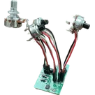
    Guitar pedal starter template based on project by Mark Wu. Includes schematic and PCB layout for basic DIY pedal hardware. This includes two 1/4" jacks (one for input and one for output), a 9V power supply (including LED), a 3PDT true bypass wiring setup, and an example potentiometer that can be copy/pasted throughout the circuit.
    The headers are meant to be unpopulated so that wires can be soldered to the pads.
    PCB design rules imported from the JLCPCB 2-layer stackup template.

    Properties

    Properties describe core aspects of the project.

    Pricing & Availability

    Distributor

    Qty 1

    Controls