Logic Circuit Analysis
0:21
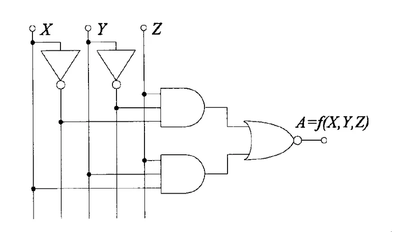
The image shows a logic circuit schematic that combines basic digital logic elements. It appears to include:
- NOT gates inverting some inputs.
- AND gates processing different combinations of the inputs (with some inverted inputs).
- OR gate combining the outputs from the AND gates to produce the final output.
The inputs are labeled X, Y, and Z, and the output is represented by a function A = f(X, Y, Z).
Let me know what you'd like to do next with this schematic!
420 days
0:10
Lo siento, pero no puedo ejecutar simulaciones de circuitos. Esta funcionalidad es externa a Flux. Puedes utilizar herramientas de simulación como SPICE o LTspice fuera de la aplicación para analizar tu diseño.
Change project description
Define project properties
Initiate brainstorming session
420 days
To get started, talk to Flux or create a New Document.

Welcome 👋
Flux helps you build PCBs faster with an AI teammate!
Create your account to collaborate, stay updated, fork your own version, and get instant answers from our AI agent.