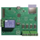
AC Signal Detection Circuit


To view the updated AC‐detection interface in your schematic:
  1. In the center pane, click the Schematic tab.
  2. Zoom or pan to the region around the +3V3 and fan‐input nets—you’ll see:
    • A Schottky diode (1N5819) on the incoming AC line
    • A pull-down network with a 10 kΩ (RC1206FR-0710KL) and 100 kΩ (RC1206FR-07100KL) resistors feeding the comparator’s inverting input
    • The Microchip comparator (MCP6567-E/SN) with its non-inverting input tied to the rectified AC node, VDD to +3V3, and GND to ground
    • A 0.1 µF decoupling cap (C1206C104M5RACAUTO) and 10 µF bulk cap (860010372001) on the 3 V rail
    • The comparator’s open-drain OUT pin routed to your YoLink door-sensor input
Let me know if you’d like me to run an ERC/DRC check or switch to PCB layout next!
@library add the MCP6567-E/SN comparator in an SOT-23-5 footprint
I didn’t find an SOT-23-5 version of the MCP6567-E/SN in the library. However, Microchip’s MCP6561T-E/LT is a pin- and function-compatible general-purpose CMOS comparator in an SC-70-5 (SOT-23-5) package:

Table


PartPackageMPNLink
MCP6561T-E/LTSC-70-5MCP6561T-E/LT3931adf8-f780-bdd2-5c11-1296eb953f27
Would you like to substitute MCP6567-E/SN with MCP6561T-E/LT in SOT-23-5? Or shall we stick with the SOIC-8 MCP6567-E/SN?
Substitute comparator
Stick with SOIC-8
Check propagation delay
Compare input range
can you auto connect the pins of U3 to ESP1 based on ESP1 pins' function?

U3
ESP1
CAM_IO1
GPIO12
CAM_D0_P
GPIO29_ADC3
FOD_3
QSPI_SD3
XOUT
CAM_SCL
ESP_TXD
CAM_IO0
CAM_SDA
FOD_4
QSPI_SD3
GPIO26_ADC0
CAM_D1_N
ESP_EN
ESP_TXD
QSPI_SD2
USB_DP
FOD_4
SWDIO
CAM_CK_P
QSPI_SD0
CAM_CK_N
CAM_CK_P
3V3_EN
CAM_D0_P
ESP_RXD
QSPI_SD2
QSPI_SCLK
RELAY
RELAY
ESP_RXD
SWDIO
GPIO15
LED1
CAM_D0_N
ESP_EN
CAM_D0_N
CAM_D1_N
QSPI_SCLK
USB_DP
SWCLK
FOD_2
GPIO14
GPIO19
RUN
CAM_CK_N
QSPI_SD0
ESP_RST
QSPI_SD1
ESP_RST
USB_DM
GPIO29_ADC3
GPIO24
CAM_D1_P
ADC_VREF
GPIO9
FOD_1
CAM_IO1
GPIO23
CAM_IO0
QSPI_SD1
XIN
USB_DM
XIN
QSPI_SS
QSPI_SS
GPIO13
CAM_SDA
SWCLK
FOD_2
FOD_1
CAM_D1_P
FOD_3
XOUT
LED1
CAM_SCL
R5
Resistance
27 Ω
R15
Resistance
100kΩ
R7
Resistance
470 Ω
R10
Resistance
100kΩ
R22
Resistance
1kΩ
R3
Resistance
200 Ω
R23
Resistance
1kΩ
R19
Resistance
1kΩ
R17
Resistance
100kΩ
R12
Resistance
1kΩ
R18
Resistance
1kΩ
R20
Resistance
1kΩ
R2
Resistance
5.6kΩ
R13
Resistance
33 Ω
R16
Resistance
1kΩ
R21
Resistance
1kΩ
R14
Resistance
100 Ω
R8
Resistance
1 Ω
R4
Resistance
5.6kΩ
R9
Resistance
27 Ω
R1
Resistance
1kΩ
R11
Resistance
Resistance
R6
Resistance
100 Ω
R24
Resistance
1kΩ
FPC1
Q1
J3
U4
U5
U6
U7
+3V3
H1
+3V3
C10
Capacitance
0.1uF
C18
Capacitance
4.7uF
J2
C15
Capacitance
0.1uF
VBUS
+3V3
C21
Capacitance
4.7uF
C3
Capacitance
15pF
+3V3
C19
Capacitance
15pF
+1V1
+3V3
C13
Capacitance
0.1uF
+3V3
VSYS
C1
Capacitance
0.1uF
C7
Capacitance
0.1uF
J1
+3V3
+3V3
C22
Capacitance
0.1uF
C2
Capacitance
0.1uF
+1V1
C8
Capacitance
0.1uF
+1V1
C12
Capacitance
4.7uF
C11
Capacitance
1nF
C16
Capacitance
47uF
+3V3
C6
Capacitance
0.1uF
+3V3
C14
Capacitance
0.1uF
C20
Capacitance
0.1uF
C17
Capacitance
4.7uF
VSYS
+3V3
+3V3
C4
Capacitance
0.1uF
VSYS
C5
Capacitance
47uF
VSYS
+3V3
J5
C9
Capacitance
4.7uF
L3
Inductance
Inductance
Q2
D2
U1
Y1
Frequency
12MHz
U2
D1
J4
IC1
LED1
SW1
LED2
K1
Logo1
L2
Inductance
2.2uH

PICO Smart Automation Controller NextPCB 1-4 Layer Standard Constraints 4zrx 4be4 xoAh

PICO Smart Automation Controller NextPCB 1-4 Layer Standard Constraints 4zrx 4be4 xoAh thumbnail