Chat

design simple bms circuit?
use mermaid formatted block diagrams to generate 2 well detailed architecture de...

@copilot use mermaid formatted block diagrams to generate 2 well detailed architecture design of this project for comparison. Make sure to use the technical and functional requirements info
1y
Creating two architecture design options for your power management board project, including technical and functional requirements, will help in visualizing the different ways the system could be structured. Below are two options using Mermaid diagram syntax:
Architecture Design Option 1: Simple Switching

Diagram


Battery Solar Panel USB 12V Output 5V Output 3.3V Output Power Inputs Battery Management IC Solar Charger USB Charger Power Selector Voltage Regulator node_12V Voltage Regulator node_5V Voltage Regulator 3.3V 12V Load 5V Load 3.3V Load LED Indicators Power Source Status Charging Status Output Status Tactile Switch
Architecture Design Option 2: Advanced with Microcontroller

Diagram


Battery Solar Panel USB Control Signals 12V Output 5V Output 3.3V Output Power Inputs Battery Management IC Solar Charger USB Charger Microcontroller Power Selector Voltage Regulator node_12V Voltage Regulator node_5V Voltage Regulator 3.3V 12V Load 5V Load 3.3V Load LED Indicators Power Source Status Charging Status Output Status Tactile Switch Data Interface Monitoring/Configuration
Summary:
  • Option 1:
    • Uses discrete components for power selection and regulation.
    • Direct paths from chargers to power selector and regulators.
    • Simple and straightforward design.
  • Option 2:
    • Integrates a microcontroller for advanced control (e.g., more precise power selection, data monitoring).
    • Additional interface for monitoring and configuration.
    • Suitable for systems requiring more flexibility and control.
Each design has its own benefits and trade-offs. Option 1 is simpler and might be more cost-effective, while Option 2 provides greater control and monitoring capabilities at the cost of added complexity. Based on your project's specific needs and constraints, one of these options can be selected or further refined.
1y
architecture 1 seems simple enough for my application. Create in the same format but with more details 3 different diagrams showing the path from the input to the 3 output for each of the input power options including proposed MPNs if you can.
1y
Let's create detailed diagrams for the power paths from each input to the outputs (12V, 5V, and 3.3V) for the simple switching architecture. We'll illustrate the paths for Battery, Solar Panel, and USB inputs using proposed Manufacturer Part Numbers (MPNs) where applicable.
Path 1: Battery Input

Diagram


Protection Diode Charging/Management 12V Output 5V Output 3.3V Output Battery Input 3.2V-4.2V LM74502 Battery Protection IC BQ24040 Battery Charger IC Power Selector TPS2115 LM2576 node_12V Regulator LM1117 node_5V Regulator LM1117 3.3V Regulator 12V Load 5V Load 3.3V Load
Path 2: Solar Panel Input

Diagram


Protection/Step-Down 12V Output 5V Output 3.3V Output Solar Panel Input node_4V-6V LT3652 Solar Charger IC Power Selector TPS2115 LM2576 node_12V Regulator LM1117 node_5V Regulator LM1117 3.3V Regulator 12V Load 5V Load 3.3V Load
Path 3: USB Input

Diagram


Protection Diode 12V Output 5V Output 3.3V Output USB Input node_5V USB Charging IC MCP73831 Power Selector TPS2115 LM2576 node_12V Regulator LM1117 node_5V Regulator LM1117 3.3V Regulator 12V Load 5V Load 3.3V Load
Proposed MPNs:
These components represent a possible selection for creating your battery, solar, and USB input power paths. Adjust component choices based on availability, cost, and specific performance requirements. Let me know if you need further help!
1y
2
, based on my requirements, help me figure out the best power architecture for t...

@copilot, based on my requirements, help me figure out the best power architecture for this project. What should the power tree look like?
1y
Based on the requirements and specifications of your Brave Power Management Board project, we can outline a general power tree architecture. Here's a step-by-step guide to help you figure it out:
Power Tree Architecture
  1. Input Stage:
    • Inputs:
      • Battery Input: 3.2V - 4.2V
      • Solar Panel Input: 4V - 6V
      • USB Input: 5V
    • Input Selection:
      • Use an automatic input selection circuit that prioritizes the highest available voltage source or, if appropriate, implements priority logic (e.g., USB > Battery > Solar).
  2. Protection Circuitry:
    • Overvoltage Protection: Add TVS diodes or similar components to protect against voltage spikes.
    • Overcurrent Protection: Implement PTC resettable fuses or current-limiting ICs for each input source.
  3. Power Conversion:
    • Buck-Boost Converters:
      • 12V Output: Use a buck-boost converter capable of outputting 12V at 500mA. This converter should be connected to the selected power input.
      • 5V Output: Use a step-down (buck) converter from the 12V output, due to higher efficiency when stepping down from a stable 12V source.
      • 3.3V Output: Again, use a step-down (buck) converter from the 5V output.
  4. Battery Charging:
    • Incorporate a battery management IC that handles charging from both solar and USB inputs.
  5. Output Regulation and Monitoring:
    • LED Indicators: Include LEDs driven by a microcontroller or a discrete control circuit to manage the status (power source, charging, and output status).
    • Output Switches/Buttons: Use MOSFETs or relays controlled by a tactile switch for each output to manage power delivery.
  6. Additional Components:
    • Voltage Regulators: Ensure that each power stage has low-dropout (LDO) regulators if needed for output stability and regulation.
    • Filtering: Use inductors and capacitors for filtering out noise and stabilizing the outputs.
Example Connection
  • From Input Selection to Converter:
    • Connect the output of the input selection circuit to the 12V buck-boost converter.
  • From Converter to Outputs:
    • Connect the 12V buck-boost converter output to the 5V buck converter.
    • Connect the 5V buck converter output to the 3.3V buck converter.
Considerations
  • Select converters and components that comply with your efficiency and environmental standards.
  • Ensure all components are rated for the specified operating temperature range (-20°C to +60°C).
Let me know if you need any further elaboration on any section or suggestions for specific components!
1y
3
R1
Resistance
500 Ω

No files yet

Documents

    Documents are markdown text files which describe project goals, capture details, or even simulation outputs.

    Assets

    power_manager_board-removebg-preview.png

    power_manager_board-removebg-preview.png

    power_manager_board-removebg-previewThumbnail
    svg

    qrcode.svg

    qrcode
    svg

    flux logo.svg

    flux logoDefault
    svg

    qrcodev2.svg

    qrcodev2
    power manager board.png

    power manager board.png

    power manager board

    IDEATION: BRAVE POWER MANAGEMENT BOARD

    IDEATION: BRAVE POWER MANAGEMENT BOARD thumbnail
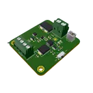
    The Brave Power Board is designed to offer multiple power outputs (12V, 5V, 3.3V) suitable for a variety of applications. It supports multiple power input sources including battery, solar panel, and USB port, providing flexibility in different operational environments. The board is particularly suitable for IoT projects where stable and reliable power supply is critical. #IoT #power #management #usb

    Properties

    Power Management

    1. Provide versatile 12V, 5V, and 3.3V power outputs. 2. Support multiple power input options: battery, solar panel, and USB port. 3. Integrate efficient solar charging capability. 4. Maintain high power conversion efficiency. 5. Ensure reliability and stability under various conditions. 6. Comply with safety and environmental standards (e.g., RoHS, WEEE). 7. Design a user-friendly interface with LED indicators and control switches. 8. Construct a robust and durable board suitable for challenging environments. 9. Implement comprehensive testing and validation protocols. 10. Deliver high-quality documentation (user manual, technical datasheet)

    1. Battery Input: 3.2V - 4.2V (Li-ion/Li-polymer battery support) 2. Solar Panel Input: 4V - 6V 3. USB Input: 5V

    - 12V Output: 500mA maximum current - 5V Output: 1.5A maximum current - 3.3V Output: 1A maximum current

    1. Solar and USB Charging: Capable of charging the battery via solar/USB input. 2. Battery Charging: Integrated charging management for safe and efficient charging.

    Operating Temperature Range: -20°C to +60°C Storage Temperature Range: -40°C to +85°C Humidity: 0% to 90% non-condensing

    - Automatic Input Selection: The board should automatically select the best available power source among battery, solar, and USB inputs. - Overvoltage Protection: Ensure protection against input voltage spikes to prevent damage to the board. - Overcurrent Protection: Include current limiting to protect the circuits from excessive current draw. - LED Indicators: Provide LED indicators for power source status, charging status, and output status. - Switches/Buttons: Include a tactile switch for power on/off control.

    Pricing & Availability

    Distributor

    Qty 1

    Controls