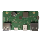
Comprehensive Test Plan Development
- Final numeric pass/fail limits still need the locked battery specification, rated PD/fast-charge profiles, and final IP5328P operating targets.
- Define the exact battery pack and rated output/input profiles.
- Add test pads for the key rails and status/control nets.
- Run ERC/DRC and update the plan with any design-specific issues found.
- Create a production test fixture checklist from this plan.
- Project: Powerbank board rnjs
- Purpose: validation plan for an IP5328P-based fully integrated bi-directional PD3.0 / fast-charge power bank board with USB-C, Micro-USB, dual USB-A outputs, button, LED indicators, NTC sensing, MOSFET power-path elements, inductor, and bulk/input/output capacitance.
- Revision: initial test plan
- Preconditions: perform schematic/ERC/DRC/manufacturing review before hardware test; confirm final BOM values, battery cell configuration, board stackup, copper thickness, enclosure, and intended rated power before production qualification.
- Assembly quality and board-level continuity checks.
- Safe first power-on and current-limited bring-up.
- Battery input/output behavior, charge path, boost/discharge path, and protection behavior around U1 IP5328P.
- USB-C, Micro-USB, and USB-A connector operation.
- LED status indicators, pushbutton behavior, and NTC temperature input behavior.
- Output regulation, current capability, ripple/noise, load transient behavior, and efficiency.
- Thermal behavior under charging, discharging, simultaneous charge/discharge, and overload conditions.
- Mechanical robustness of connectors, button, board fit, and solder joints.
- Environmental screening suitable for a portable battery-powered consumer device.
- Manufacturing, reliability, and field-edge-case coverage.
- Formal USB-IF certification.
- Full IEC 62368-1 / CE / FCC / UN 38.3 / battery-pack certification.
- Production ATE fixture implementation details beyond strategy and recommended coverage.
- Cell-level qualification unless the battery pack and protection circuit are specified.
- Verify the board can be powered safely without shorts, latch-up, smoke, overheating, or abnormal standby current.
- Verify U1 IP5328P manages charge, boost, fast-charge negotiation, user button input, LED indication, and NTC-based thermal response as intended.
- Verify all external ports provide the required electrical behavior and survive realistic plug/unplug and fault cases.
- Verify thermal margins under worst-case load and charge conditions.
- Verify mechanical durability of connectors and user controls.
- Verify the design is manufacturable and repeatable with clear pass/fail criteria.
- Identify gaps requiring design changes before production.
Table
| ID | Requirement | Validation Method | Pass Criteria |
|---|---|---|---|
| F-01 | Board accepts power from USB-C input path and/or Micro-USB input path as designed | Input power tests | Charging or input-current behavior starts without fault; input current and rail voltage remain within final spec |
| F-02 | Board supplies regulated USB output power on USB-A ports J3/J4 | Load testing | Output voltage remains within USB/fast-charge profile tolerance at rated load |
| F-03 | USB-C connector J2 supports intended bi-directional power role/PD or fast-charge behavior | PD analyzer and sink/source tests | Advertised/accepted profiles match final requirements; no unsafe voltage on wrong pins |
| F-04 | U1 IP5328P controls charge/discharge without thermal runaway or oscillation | Charge/discharge cycling | Stable operation across battery voltage range and load steps |
| F-05 | LEDs D1-D4 indicate status consistently | Functional observation | LED patterns match IP5328P behavior and user documentation |
| F-06 | Button SW1 triggers intended wake/mode/status function | Functional observation | Press/release events reliably detected without false triggers |
| F-07 | NTC RNTC1 provides thermal protection input | Simulated NTC/temperature test | Charge/discharge derates or stops at expected hot/cold thresholds after final threshold confirmation |
| F-08 | MOSFET power-path/control devices Q1-Q4 switch safely | Scope and thermal tests | Correct gate/drain/source states; no overheating at rated current |
Table
| ID | Requirement | Validation Method | Pass Criteria |
|---|---|---|---|
| NF-01 | Electrical safety | Shorts, current-limit, fault injection | No fire, smoke, damaged connector, or sustained unsafe temperature during defined faults |
| NF-02 | Thermal reliability | Thermal chamber / IR camera | Components remain below their rated temperature with margin; enclosure touch temperature acceptable |
| NF-03 | Mechanical robustness | Connector/button cycling | No intermittent connection or mechanical damage after test cycles |
| NF-04 | EMI/noise readiness | Scope near-field pre-scan | Switching noise and conducted ripple acceptable for intended product class; no excessive ringing |
| NF-05 | Manufacturing repeatability | ICT/functional test | All production-critical nets/components have test access or defined functional verification |
| NF-06 | User reliability | Edge-case testing | Recovers from brownout, overload, repeated plug/unplug, and simultaneous port usage |
- Current-limited DC bench supply, 0-20 V, >=5 A recommended.
- Electronic load, constant-current/constant-power, >=5 A per output path or above final rating.
- USB-C PD analyzer/source/sink emulator.
- USB power meter/load trigger modules for 5 V / 9 V / 12 V / higher profiles if supported by the final design.
- Digital multimeter and milliohm/continuity capability.
- Oscilloscope >=100 MHz with short ground spring probes.
- Thermal camera or thermocouples with data logger.
- Battery simulator or protected Li-ion/LiPo test pack with fuse and current logging.
- Environmental chamber if available.
- ESD gun and surge/transient equipment for pre-compliance if available.
- Safety: fire-resistant Li-ion test bag/box, fused battery leads, eye protection, nonflammable bench surface.
- USB-C cable set rated for required current and e-marker state where applicable.
- Micro-USB cable rated for intended input current.
- USB-A breakout and load cables.
- Kelvin clips or test points for battery rail/current measurement.
- Thermocouples on U1, L1, Q1-Q4, USB connectors, bulk capacitor C12, and battery connector/leads.
- Optional automated relay matrix for port insertion, load switching, and fault injection.
- BOM is locked for the test build.
- Schematic ERC and layout DRC are reviewed.
- Battery cell/pack chemistry, voltage range, protection, capacity, and current rating are documented.
- Rated input/output profiles and maximum load current are documented.
- Test operator has a safe shutdown procedure.
- 100% of mandatory bring-up/electrical tests pass on at least one engineering sample.
- No unresolved safety-critical failures.
- Thermal worst-case tests show adequate margin.
- Mechanical tests do not create intermittent faults.
- Any deviations are logged with root cause, corrective action, and retest evidence.
Table
| Test ID | Test Case | Method | Expected Outcome | Pass/Fail Criteria |
|---|---|---|---|---|
| A-01 | Visual inspection | Microscope inspect U1, connectors J1/J2/J3/J4, Q1-Q4, L1, C12, LEDs, SW1, RNTC1, all passives | Correct placement, no bridges, no tombstones, no cracked parts | Pass if no visible defect; fail if any solder bridge, wrong orientation, cracked component, lifted pad, or missing part |
| A-02 | Polarity/orientation check | Verify LEDs D1-D4, electrolytic C12, USB connectors, MOSFET orientation | All polarized parts match assembly drawing | Pass if all orientations match; fail on any reversed part |
| A-03 | Connector solder integrity | Inspect and gently probe connector shells and pins | No movement, full wetting | Pass if no cracked joints or movement; fail if any connector pin/shell is loose |
| A-04 | ICT continuity | Continuity from each connector pin to destination nets and shells to ground/chassis as designed | All pins connected only where intended | Pass if continuity/open/short matches netlist; fail if any open or unintended short |
| A-05 | Power rail resistance before power | Measure BAT/VBUS/USB output rails to GND | No low-resistance short | Pass if resistance is not a hard short; investigate any rail below a project-defined threshold such as <10 ohm before power |
Table
| Test ID | Test Case | Method | Expected Outcome | Pass/Fail Criteria |
|---|---|---|---|---|
| B-01 | First power-on with current limit | Use bench supply/battery simulator at minimum safe voltage and low current limit | No smoke, no rapid current rise, U1 remains cool | Pass if input current is stable and below expected idle/standby limit; fail if current limit is hit, device overheats, or output rails are abnormal |
| B-02 | Battery rail range | Sweep battery simulator across final cell voltage range | Board stays in valid state and transitions cleanly | Pass if no latch-up or abnormal current over full final battery range |
| B-03 | USB-C input charge behavior | Connect PD/USB-C source via J2 | Board negotiates/accepts intended input profile | Pass if voltage/current profile matches final spec and remains stable |
| B-04 | Micro-USB input charge behavior | Connect 5 V input via J1 | Board charges or powers input path per design | Pass if input current, temperature, and status indication match final spec |
| B-05 | USB-A output no-load voltage | Enable output and measure J3/J4 VBUS | Output appears only when expected | Pass if no-load voltage is within required tolerance and no unintended output when off |
| B-06 | USB-A rated load | Apply rated load to J3 and J4 individually and together | Output remains regulated | Pass if VBUS remains within final USB/fast-charge tolerance, no reset/oscillation, and component temperatures are acceptable |
| B-07 | Load transient | Step load 10%-90%-10% of rated current | Stable regulation and recovery | Pass if voltage dip/overshoot and settling meet final requirement; fail on reset, latch-off, or excessive overshoot |
| B-08 | Output ripple/noise | Scope output with short ground at J3/J4 and bulk caps | Ripple within switching regulator target | Pass if ripple is below final limit; use provisional target <100 mVpp at 5 V unless product spec states otherwise |
| B-09 | Efficiency | Measure battery input power vs USB output power at 25%, 50%, 100% load | Efficiency consistent with IP5328P design expectations | Pass if above final efficiency target and no thermal issue |
| B-10 | Short-circuit protection | Momentarily short each output through controlled fixture/current monitor | Protection activates safely | Pass if output current limits/latches off safely and recovers as specified; fail if connector, trace, MOSFET, or U1 overheats/damages |
| B-11 | Overload protection | Increase load above rated value gradually | Controlled limit or shutdown | Pass if output does not exceed safe current/temperature and recovers after overload removal |
| B-12 | Reverse/backfeed check | Apply voltage to output port with main source off using protected setup | No unsafe backfeed | Pass if backfeed current is below final safe limit and no other port becomes dangerously energized |
| B-13 | Standby/quiescent current | Measure battery current with no cable/load after timeout | Low standby consumption | Pass if below final standby-current requirement; fail if excessive battery drain |
Table
| Test ID | Test Case | Method | Expected Outcome | Pass/Fail Criteria |
|---|---|---|---|---|
| C-01 | USB-C CC/PD negotiation | Use PD analyzer on J2 | Correct source/sink role and advertised profiles | Pass if profiles and role behavior match requirements; fail if wrong voltage is advertised or negotiation is unstable |
| C-02 | Fast-charge detection on USB-A | Use compatible load trigger / protocol analyzer | Intended fast-charge mode is recognized | Pass if expected 5 V / higher-voltage or current mode is negotiated per final spec |
| C-03 | Cable attach/detach debounce | Repeatedly plug/unplug USB-C, Micro-USB, and USB-A | No latch-up or false permanent fault | Pass if board recovers every cycle and LEDs/status remain correct |
| C-04 | Dual-port behavior | Load both USB-A ports and USB-C path according to intended role | Power sharing behaves as designed | Pass if combined current limit and priority behavior match final requirements |
| C-05 | LED user interface | Observe D1-D4 during charge, discharge, full, low battery, fault | Status is clear and repeatable | Pass if LED state table matches user documentation and IP5328P behavior |
| C-06 | Button user interface | Short/long press SW1 in standby, charging, discharging, fault | Correct state transitions | Pass if every press length maps to expected behavior with no bounce-induced extra events |
Table
| Test ID | Test Case | Method | Expected Outcome | Pass/Fail Criteria |
|---|---|---|---|---|
| D-01 | Thermal baseline | No load/standby at room temperature | No unexpected hot components | Pass if all components remain near ambient; fail if any active part rises unexpectedly |
| D-02 | Max charge thermal | Charge at maximum supported input current | Stable temperatures | Pass if U1, L1, Q1-Q4, connectors, and C12 remain below component ratings with margin |
| D-03 | Max discharge thermal | Full-rated USB output load until thermal equilibrium | Stable temperatures | Pass if no thermal shutdown unless specified and touch/component temperatures meet limits |
| D-04 | Simultaneous charge/discharge | Input active while output load active if supported | Controlled power path | Pass if temperatures and current paths remain safe |
| D-05 | Enclosure worst case | Test inside intended enclosure with minimal airflow | No unsafe touch or component temperatures | Pass if enclosure and components meet final safety limits |
| D-06 | NTC response | Heat/cool RNTC1 or substitute resistor values | U1 limits/stops operation as intended | Pass if hot/cold thresholds trigger correct protection behavior after threshold confirmation |
Table
| Test ID | Test Case | Method | Expected Outcome | Pass/Fail Criteria |
|---|---|---|---|---|
| E-01 | Connector insertion/removal | Cycle J1, J2, J3, J4 with rated cables | No damage or intermittent contact | Pass if all ports still pass electrical tests after cycling; fail on looseness/intermittence |
| E-02 | Connector side-load | Apply controlled cable side load within connector rating | Connector and solder joints hold | Pass if no cracked solder, lifted pads, or intermittent power |
| E-03 | Button life check | Cycle SW1 repeatedly | Reliable actuation | Pass if switch still actuates and resistance/contact behavior remains normal |
| E-04 | Board/enclosure fit | Install in intended enclosure | No connector misalignment or mechanical stress | Pass if ports align and board is not bent/stressed |
| E-05 | Drop/vibration screen | Controlled non-destructive handling/drop screen for prototype | No intermittent connection | Pass if post-test visual and electrical tests pass |
Table
| Test ID | Test Case | Method | Expected Outcome | Pass/Fail Criteria |
|---|---|---|---|---|
| F-ENV-01 | Low-temperature startup | Cold soak to final low operating temp; power on | Starts safely | Pass if charge/discharge behavior follows spec and NTC protection works |
| F-ENV-02 | High-temperature operation | Hot soak to final high operating temp; run load/charge | No unsafe heating or permanent fault | Pass if protection activates when required and recovers after cooldown |
| F-ENV-03 | Temperature cycling | Cycle between low/high operating temperatures | No cracked joints or drift | Pass if all functional tests pass after cycling |
| F-ENV-04 | Humidity soak | 40-60 C / high RH pre-screen if available | No corrosion/insulation failure | Pass if leakage/current and function remain acceptable |
| F-ENV-05 | ESD pre-compliance | Contact/air discharge to USB shells, button, exposed metal | Survives expected user ESD | Pass if no permanent failure, reset acceptable only if self-recovers; fail on damage or unsafe output |
| F-ENV-06 | Storage leakage | Store charged battery connected for defined period | Low battery drain | Pass if capacity loss due to board standby is within final requirement |
Table
| Test ID | Test Case | Method | Expected Outcome | Pass/Fail Criteria |
|---|---|---|---|---|
| G-01 | Brownout recovery | Ramp battery voltage down/up slowly | Clean shutdown and restart | Pass if no latch-up and no repeated unsafe oscillation |
| G-02 | Hot-plug under load | Plug/unplug loads at high current | Controlled transient response | Pass if no connector arcing damage, no U1 latch-up, and output recovers |
| G-03 | Input overvoltage screening | Apply only within safe/datasheet-limited range using current limit | Protection/no damage | Pass if board handles allowed max input; do not exceed datasheet limits |
| G-04 | Output short repeated | Repeat short/recovery cycles | Protection is repeatable | Pass if no progressive heating or permanent damage |
| G-05 | Thermal fault recovery | Trigger hot NTC condition then cool | Fault clears as designed | Pass if operation resumes only after safe threshold |
| G-06 | Multi-port contention | Multiple chargers/loads connected in unusual order | Safe priority behavior | Pass if no port backfeeds another and no unsafe voltage appears |
| G-07 | Partial assembly fault screen | Missing/incorrect LED/passive non-critical cases for production diagnostics | Manufacturing test catches issue | Pass if ICT/functional test flags defect |
Table
| Measurement | Location | Provisional Expected Value | Pass Criteria |
|---|---|---|---|
| Battery rail | Battery input / U1 BAT-related pins | Final single-cell Li-ion range, typically about 3.0-4.2 V if single-cell | Within finalized battery spec only |
| USB output VBUS | J3/J4 VBUS to GND | 5 V nominal unless fast-charge profile selected | Within USB/profile tolerance under rated load |
| USB-C VBUS | J2 VBUS to GND | Depends on negotiated role/profile | Must match PD/fast-charge negotiation and never appear unexpectedly |
| Micro-USB input | J1 VBUS to GND | 5 V nominal input | Stable and within input tolerance |
| Output ripple | J3/J4 VBUS with rated load | Provisional <100 mVpp at 5 V | Replace with final requirement after validation |
| U1 temperature | U1 package top | Below datasheet max with design margin | No thermal shutdown during rated use unless operating outside spec |
| Inductor temperature | L1 body | Below inductor rating with margin | No saturation symptoms or excessive heating |
| MOSFET temperature | Q1-Q4 packages | Below device rating with margin | No localized hot spot or discoloration |
| NTC resistance | RNTC1 node | Follows NTC curve | Thermal thresholds match design intent |
- Use a Python-controlled test bench with SCPI instruments: bench supply, electronic load, DMM, oscilloscope, thermal logger, and PD analyzer if supported.
- Record every test with timestamp, board serial number, firmware/config revision if any, cable type, battery simulator profile, ambient temperature, and operator.
- Automate sweeps: battery voltage, load current, load transient, input voltage, charge/discharge duration, and thermal soak snapshots.
- Generate CSV logs and automatic pass/fail reports.
- Add or use accessible test pads for GND, battery rail, USB output rails, key U1 control/status pins, LED lines, button node, NTC node, and high-current path sense points.
- Use ICT for opens/shorts/component presence where feasible.
- Use short functional test: no-short check, input current, output 5 V enable, LED/button check, NTC simulation, each connector continuity, and a brief load pulse.
- Use golden-board comparison limits for currents and voltages after at least 5-10 known-good boards are characterized.
Table
| Risk | Impact | Mitigation |
|---|---|---|
| Missing finalized power ratings | Test limits may be too loose or too strict | Freeze requirements before qualification; update numeric criteria |
| Li-ion battery hazards | Fire or cell damage | Use protected pack/battery simulator, fusing, current limits, fire-safe enclosure |
| USB-C/fast-charge negotiation errors | Device incompatibility or unsafe voltage | Use PD analyzer and test multiple real chargers/cables/loads |
| High-current PCB heating | Reliability failure | Thermal test in enclosure and inspect copper/current paths |
| Connector mechanical stress | Field failures | Side-load/cycling tests and add mechanical reinforcement if needed |
| Insufficient test access | Low production coverage | Add test pads for rails/status/control nodes before layout freeze |
| NTC threshold mismatch | Unsafe operation at temperature extremes | Validate RNTC1 curve and divider/thresholds against IP5328P datasheet |
| Backfeed between ports | Damage to connected devices | Explicit reverse/backfeed and multi-port contention tests |
- Add labeled test pads for battery rail, GND, USB output VBUS rails, USB-C VBUS, Micro-USB VBUS, NTC node, button node, and LED/status nets.
- Define final rated input/output profiles, maximum continuous current, battery pack type, capacity, and allowed operating temperature range.
- Create a power/thermal budget and compare expected current against connector, MOSFET, inductor, trace, and capacitor ratings.
- Add fusing or resettable protection on battery/input paths if not already covered by the pack and U1 reference design.
- Validate USB-C CC/PD implementation with a protocol analyzer before ordering many boards.
- Run at least 3 engineering samples through full electrical/thermal tests and at least 10 pilot units through production functional tests.
- Keep a failure log with photos, scope captures, thermal images, and corrective action.
- Do not perform destructive fault tests with an unprotected Li-ion cell; use a current-limited simulator first.
Table
| Section | Result | Notes |
|---|---|---|
| Visual / Assembly | [ ] Pass / [ ] Fail | |
| Electrical Bring-Up | [ ] Pass / [ ] Fail | |
| USB-C / USB-A / Micro-USB Interfaces | [ ] Pass / [ ] Fail | |
| Charge / Discharge Function | [ ] Pass / [ ] Fail | |
| Protection / Fault Handling | [ ] Pass / [ ] Fail | |
| Thermal | [ ] Pass / [ ] Fail | |
| Mechanical | [ ] Pass / [ ] Fail | |
| Environmental | [ ] Pass / [ ] Fail | |
| Production Test Readiness | [ ] Pass / [ ] Fail |
0. Document Control
1. Testing Scope
In Scope
Out of Scope Until Requirements Are Finalized
2. Test Objectives
3. Functional and Non-Functional Requirements to Validate
Functional Requirements
Non-Functional Requirements
4. Required Test Environment
Bench Equipment
Fixtures and Accessories
5. General Entry and Exit Criteria
Entry Criteria
Exit Criteria
6. Test Categories and Test Cases
A. Visual, Assembly, and Manufacturing Tests
B. Electrical Bring-Up and Power Testing
C. Communication and Interface Testing
D. Thermal Testing
E. Mechanical Testing
F. Environmental and Reliability Testing
G. Protection, Fault, and Edge-Case Testing
7. Expected Measurement Reference
8. Automation Strategy
Prototype Automation
Production Test Strategy
9. Key Risks and Mitigations
10. Recommendations to Improve Coverage and Reliability
11. Pass/Fail Summary Template