Chat

Welcome to Flux

Treat Flux like your intern. Tell it what you'd like to build and it'll get to work. You can also ask it questions, brainstorm ideas, and teach it your preferences. Learn More

Explain project
Write a project description
Find schematic issues
Create a test plan
Simulate a circuit
Prepare for Manufacturing
Component Selection Workflow
New Subsystem Wizard
Write I2C initialization code
Generate firmware skeleton
U1
what does this chip do. explain th epins

@copilot what does this chip do. explain th epins
1y
The MAX485EESA+\text{MAX485EESA+} is a low-power, high-speed RS-485/RS-422 transceiver. It's typically used for communication over long distances in noisy environments, such as in industrial settings or for networking between computers and peripherals.
Here's a breakdown of its pins:
  1. RO (Pin 1) - Receiver Output: This pin outputs the received data to the microcontroller or other logic device.
  2. ~RE (Pin 2) - Receiver Enable (Active Low): This pin enables the receiver when it is low. When high, the receiver is disabled.
  3. DE (Pin 3) - Driver Enable: This pin enables the driver when it is high. When low, the driver is disabled.
  4. DI (Pin 4) - Driver Input: This pin accepts the data to be transmitted.
  5. GND (Pin 5) - Ground: This is the reference ground pin for the device.
  6. A (Pin 6) - Non-Inverting Receiver Input/Driver Output: This is one of the differential data lines.
  7. B (Pin 7) - Inverting Receiver Input/Driver Output: This is the other differential data line.
  8. VCC (Pin 8) - Supply Voltage: This pin powers the device, typically connected to a 5V supply.
Functionality:
  • Driver Function: When the driver is enabled by setting DE high, it takes data from DI pin and sends it differentially across A and B pins.
  • Receiver Function: When the receiver is enabled by setting ~RE low, it receives differential signals from A and B and converts them to a single-ended output on the RO pin.
This setup allows for full-duplex communication but is typically used in half-duplex mode (bidirectional but not simultaneous) given RS-485 capabilities. Let me know if you need further clarification or have other questions!
1y
1
SCL
J2
R2
Resistance
500 ฮฉ
RESET
VIN
IC1
SDA
C1
Capacitance
Capacitance
Net1
Outline
SCL
J3
J4
SDA
Net1
+3V3
+5V
J1

To get started, talk to Flux or create a New Document.

Documents

    Documents are markdown text files which describe project goals, capture details, or even simulation outputs.

    Assets

    step

    Arduino UNO.STEP

    Arduino UNO 3D3D Model
    dxf

    Arduino UNO R3 shield - Shape.dxf

    Arduino UNO R3 shield - Shape
    Arduino Uno R3 Shield Template-removebg-preview.png

    Arduino Uno R3 Shield Template-removebg-preview.png

    Arduino Uno R3 Shield Template-removebg-previewThumbnail

    Arduino Uno R3 Shield Template 5RoN

    Arduino Uno R3 Shield Template 5RoN thumbnail
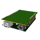
    Template for Arduino Uno R3 Shield. Include an official pinout so you will always know Arduino names, the alternative roles of pins, which one is SDA, or SCL, etc. On PCB you can find the 3D model of the Arduino Uno R3 itself along with the board outline on the silkscreen. #Arduino #Uno #Shield #Template #project-template #project

    Properties

    Properties describe core aspects of the project.

    Pricing & Availability

    Distributor

    Qty 1

    Arrow

    $3.98

    Digi-Key

    $13.15โ€“$17.50

    LCSC

    $18.09

    Mouser

    $21.60

    Controls