DC Motor Driver Schematic Review
Thought for 28 sec
Here’s what the Flux documentation says about adding a pad (including vias):
- Right click the PCB canvas to trigger the Context Menu.
- Hover over Add in the Context Menu to reveal a submenu.
- Click Pad in the submenu.
From the PCB Object List:
- In the list, locate the object under which you'd like to add the pad.
- If you're making a board, this is most likely the Layout object.
- If you're making a component, this is most likely the Footprint object.
- Click on the ... icon to the right of the object's name, or right click the object, to trigger the Context Menu.
- Hover over Add in the Context Menu to reveal a submenu.
- Click Pad in the submenu.
Source: Flux Docs – Pads and Holes

How to change dimensions of the pcb?
Thought for 26 sec
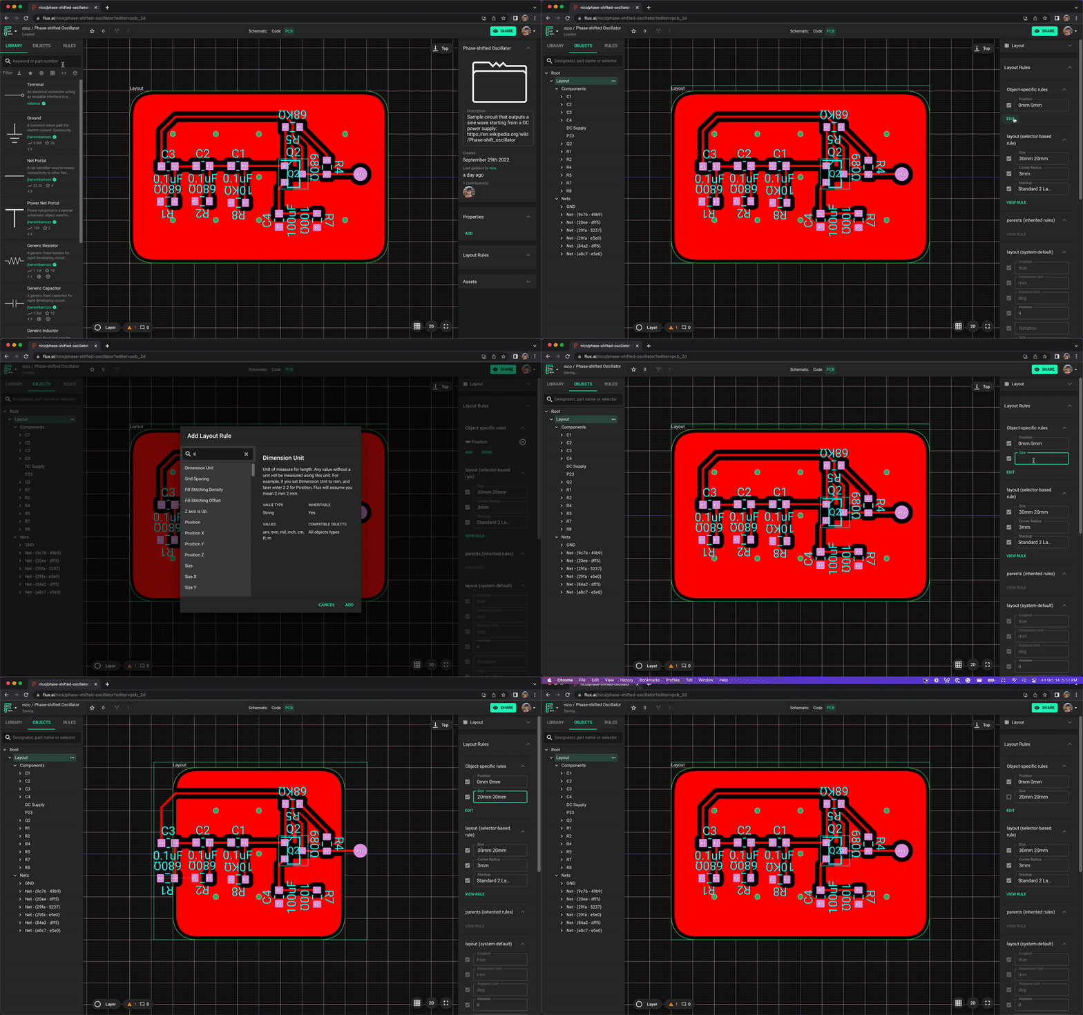
Here’s what the Flux documentation says about changing your board’s dimensions:
"1. In the left-hand panel, select the "Objects" tab and choose the "Layout" object
1. For the layout object to appear, there must be at least one part in the schematic
- On the right-side panel, find "Object-Specific Rules". Click on "Edit", "Add" and search for the rule "Size"
- Type the desired size
- You can specify the units by adding "mm", "in" or "mil"
- You can add two values separated by a space for x and y sizes. For example,
20mm 10mmmeans an x size of 20mm and y size of 10mm
Image
Ask about custom outline
Clarify non-rectangular shapes
Board size units
Per-module outlines
Minimum size limits
