Chat

Welcome to Flux

Treat Flux like your intern. Tell it what you'd like to build and it'll get to work. You can also ask it questions, brainstorm ideas, and teach it your preferences. Learn More

Explain project
Write a project description
Find schematic issues
Create a test plan
Simulate a circuit
Prepare for Manufacturing
Component Selection Workflow
New Subsystem Wizard
I need to break down this circuit diagram into functional blocks. Please analyze...

@copilot I need to break down this circuit diagram into functional blocks. Please analyze the it, identify the different functional parts and DO NOT ASSUME ANY PART/COMPONENT. Here is a list of common module names: Power Supply Functional Blocks
Amplifier Functional Blocks
Oscillator Functional Blocks
Filter Functional Blocks
Signal Processing Functional Blocks
Signal Conditioning Functional Blocks
Modulation and Demodulation Functional Blocks
Communication Functional Blocks
Control Functional Blocks
Sensor Interface Functional Blocks
Protection Functional Blocks
If you find a part relevent to a perticular module name then you use it otherwise you do not use it. Create individual tables for each identified module with the following details: Module Name
Components
Description of Functionality
Connections and Interactions with Other Modules
Please provide the response in a Table Format
2y
Certainly! I'll break down the circuit diagram into functional blocks based on the given components and their functionalities.
1. Power Supply Functional Blocks

Table


Module NameComponentsDescription of FunctionalityConnections and Interactions with Other Modules
Power SupplyVCC, VIO, C1, C2, C3, C10Provides voltage to the system components. Capacitors used for filtering and stabilization.- VCC: Connected to various components to provide power (e.g., U1:VCC, MCU1:5). - VIO: Interfaces with other functional blocks like U1:VIO, MCU2:5. - C1, C2, C3, C10: Filter the voltage supply and stabilize it across the circuit.
2. Protection Functional Blocks

Table


Module NameComponentsDescription of FunctionalityConnections and Interactions with Other Modules
ProtectionD1, D2Provide ESD and transient protection for CAN bus lines.- D1 (NUP2105L): Protection Diode on CANH2 and CANL2 lines. - D2 (NUP2105L): Protection Diode on CANH1 and CANL1 lines. - Connected to CANBUS lines and ground.
3. Communication Functional Blocks

Table


Module NameComponentsDescription of FunctionalityConnections and Interactions with Other Modules
CAN TransceiverU1 (TJA1059TKJ), R1, R2, R3, R4Handles CAN bus communications for dual channels. Resistors for termination and pull-up/down.- U1 (TJA1059TKJ): Dual CAN transceiver with various connections to MCU and CANBUS lines. - Resistors: R1 (30Ω), R2 (30Ω), R3 (30Ω), R4 (30Ω) provide termination for CAN bus lines. - Connects to MCU pins for TXD/RXD signals and CANBUS connectors.
4. Control Functional Blocks

Table


Module NameComponentsDescription of FunctionalityConnections and Interactions with Other Modules
ControlSTBY1, STBY2Control the standby function of the CAN transceiver.- STBY1 & STBY2: Connected to U1 to control standby modes of CAN1 and CAN2. Controlled by MCU for enabling/disabling transceiver functionalities.
5. Communication Interface Functional Blocks

Table


Module NameComponentsDescription of FunctionalityConnections and Interactions with Other Modules
Communication InterfaceCANBUS1, CANBUS2, CANH1, CANH2, CANL1, CANL2, CAN_RX1, CAN_RX2, CAN_TX1, CAN_TX2Interface between the CAN transceiver and external CAN networks.- CANBUS1, CANBUS2: Connect to external CAN networks. - CANH1, CANH2, CANL1, CANL2: Line connections for CAN bus high and low signals. - CAN_RX1, CAN_RX2, CAN_TX1, CAN_TX2: Communication lines between MCUs and CAN transceiver U1.
6. Signal Conditioning Functional Blocks

Table


Module NameComponentsDescription of FunctionalityConnections and Interactions with Other Modules
Signal ConditioningC4, C5, C6, C7, C8, C9Filter and stabilize signal lines associated with CAN bus communication.- C4, C5, C6, C7, C8, C9: Capacitors for filtering high-frequency noise on CAN bus lines and power lines. - Placement directly on CANH1, CANH2, CANL1, CANL2, and associated nets.
7. MCU Interface Functional Blocks

Table


Module NameComponentsDescription of FunctionalityConnections and Interactions with Other Modules
MCU InterfaceMCU1, MCU2Interface between the CAN transceiver and the microcontrollers handling logic and control for CAN communication.- MCU1: Interfaces with CAN1 (TXD1, RXD1) and control lines (STBY1). - MCU2: Interfaces with CAN2 (TXD2, RXD2) and control lines (STBY2). - Interacts primarily with U1 for CAN transmissions and receptions.
The breakdown categorizes each part and its relevance in the broader context of the schematic, identifying all essential functional blocks. Let me know if you need further elaboration on any specific connection or block.
2y
What do we have for voltage spike protection?
2y
For voltage spike protection in the circuit, the following components are used:
Protection Functional Blocks

Table


Module NameComponentsDescription of FunctionalityConnections and Interactions with Other Modules
ProtectionD1, D2Provide ESD and transient voltage spike protection for CAN bus lines.- D1 (NUP2105L): Protection diode connected to CANH2 and CANL2 lines. - D2 (NUP2105L): Protection diode connected to CANH1 and CANL1 lines. - Connects to CANBUS lines and ground, providing clamping for voltage spikes on the CAN lines.
Voltage Spike Protection Details
  • D1 (NUP2105L):
    • Connections:
      • D1:K1D1:K1 to CANBUS2:P2CANBUS2:P2
      • D1:K2D1:K2 to CANH2:P1CANH2:P1
      • D1:AD1:A to GND
  • D2 (NUP2105L):
    • Connections:
      • D2:K1D2:K1 to CANBUS1:P2CANBUS1:P2
      • D2:K2D2:K2 to CANH1:P1CANH1:P1
      • D2:AD2:A to GND
These diodes are designed to clamp voltage spikes and prevent high voltage transients from damaging the sensitive electronics in the CAN transceiver and other connected components. They typically handle ESD and other transient events that can occur on CAN bus lines in automotive and industrial environments.
2y
1

No files yet

Documents

    Documents are markdown text files which describe project goals, capture details, or even simulation outputs.

    Assets

    TJA1059TKJ Reference Design-removebg-preview.png

    TJA1059TKJ Reference Design-removebg-preview.png

    TJA1059TKJ Reference Design-removebg-previewThumbnail

    TJA1059TKJ Reference Design

    TJA1059TKJ Reference Design thumbnail
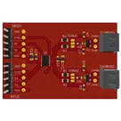
    This is a reference design for TJA1059TKJ Dual high-speed CAN transceiver with Standby mode. It offers advanced features, such as wake-up capability and high-speed data rates, making it suitable for automotive and industrial applications. #MCP25612FD #CANbus #transceiver #highspeed #automotive #referenceDesign #project #CANbus #interface #transceiverCircuit #TJA1059TKJ #referenceDesign #canbus #nxp #template #reference-design

    Pricing & Availability

    Distributor

    Qty 1

    Arrow

    $2.08

    Digi-Key

    $1.44–$2.08

    LCSC

    $4.09–$4.52

    Mouser

    $3.43

    Verical

    $1.64–$2.23

    Controls