Project Overview and Features

2:51

Gathering project details.

Formulating queries for project overview.

Defining project intents.

Linking components correctly.

Summarizing project features and details.

Accessing knowledge base.

Reviewing the bill of materials.

Running design review.

Detailing project components and layout.

Here’s a clear overview of what this project is, what it does, and its main building blocks.
What it does
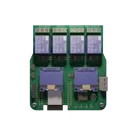
  • Purpose: Dual-tank water level monitor using two ultrasonic sensors and an ESP32. It can display/report levels and drive external loads via relay outputs for automation.
  • Power: Designed around a wide “7–30 V” input net that is stepped to 5 V and then to 3.3 V for the ESP32 and logic.
  • Interfaces: Two dedicated ultrasonic sensor ports, two I2C expansion sockets (e.g., for an OLED), a UART/programming header, and two full 2x10 headers that break out ESP32 IO.
Main components and functions

Table


Main components and functions
U1
U2 + power stage: L1, D5, bulk/decoupling caps (C5, C6, C9)
U12 + 3V3 decoupling (C1, C7, C8)
Dual ultrasonic sensor connector J11
I2C expansion sockets J5, J6
Power terminal J4
4x modular relays RL1, RL2, RL3, RL4
Per-relay status LEDs LED1, LED2, LED3, LED4 with series resistors R7, R8, R9, R10
Programming/UART header J3
Full IO breakout headers J1, J2
Tact switches EN, IO0 + pull parts R6, R5
How it works (signal mapping)
  • Ultrasonic ports (two independent channels)
    • Sensor 1: Trigger “SENSE_TRIGGER 1” -> U1 IO19; Echo “SENSE_ECHO 1” -> U1 IO5. Routed through J11.
    • Sensor 2: Trigger “SENSE_TRIGGER 2” -> U1 IO27; Echo “SENSE_ECHO 2” -> U1 IO13. Routed through J11.
    • Power to sensors from 5 V and GND on the same 6-pin socket.
  • I2C expansion
    • SDA -> U1 IO21; SCL -> U1 IO22 available on J5 and J6, with 5 V and GND.
  • Relays
    • RL1 IN -> U1 IO26; RL2 IN -> U1 IO25; RL3 IN -> U1 IO33; RL4 IN -> U1 IO32. All relays powered from 5 V, GND common.
    • Status LED cathodes tie to relay indicator nets; anodes go to 5 V through R7R10.
  • UART/programming
    • J3: TXD0, RXD0, 5 V, GND, and IO0. R5 pulls IO0 up; the IO0 can force boot mode.
    • EN line pulled up by R6; the EN resets.
  • Power path
    • Input on “7–30 V” via J4 -> U2 buck -> 5 V net -> U12 -> 3V3 net.
    • Energy storage/decoupling at input/output: C5, C6, C9, C1, C7, C8; rectifier D5; inductor L1.
Coolest features
  • Dual ultrasonic channels with dedicated Trigger/Echo lines and power on a single 6-pin socket.
  • Four on-board, 5 V relay modules with per-channel status LEDs for immediate visual feedback.
  • Wide-input power design with on-board 5 V buck and 3.3 V LDO rails, so the system can be powered from a broad range (net labeled “7–30 V”).
  • Two I2C sockets for drop-in peripherals like an OLED or extra sensors.
  • Full ESP32 breakout via two 2x10 headers, plus a clean UART/programming header and boot/reset buttons.
  • Mounting holes (M3) for easy enclosure integration.
Current design health (automated checks)
  • Manufacturing: Many generics lack MPNs (e.g., resistors, capacitors, some connectors, inductor). This is flagged under “Manufacturer Part Number” and will need real parts assigned before ordering.
  • Layout: “Floating copper” and “Layers with Multiple Fills” errors, and “Overlapping Copper” warnings are present. These should be resolved before fabrication.
  • Missing-parts checks (e.g., decoupling/pull-ups) haven’t been run by the automated assistants, but the schematic already includes pull-ups for EN/IO0 and multiple decoupling capacitors.
If you want, I can help you: assign concrete MPNs to the generics, validate the ultrasonic header pinout against your sensors, and prepare the board for manufacture (resolve DRC errors, finalize footprints).
Clarify ultrasonic headers
Choose ultrasonic model
Resolve DRC copper issues
Assign real MPNs
Power-stage validation
142 days


  • Ground
    A common return path for electric current. Commonly known as ground.
  • Net Portal
    Wirelessly connects nets on schematic. Used to organize schematics and separate functional blocks. To wirelessly connect net portals, give them same designator. #portal
  • Power Net Portal
    Wirelessly connects power nets on schematic. Identical to the net portal, but with a power symbol. Used to organize schematics and separate functional blocks. To wirelessly connect power net portals, give them the same designator. #portal #power
  • Generic Resistor
    A generic fixed resistor ideal for rapid circuit topology development. Its footprint automatically adapts based on the selected package case code—supporting 0402, 0603, 0805, 1203, and many other standard SMD packages, as well as axial horizontal and vertical configurations. Save precious design time by seamlessly add more information to this part (value, footprint, etc.) as it becomes available. Standard resistor values: 1.0 ohm, 10 ohm, 100 ohm, 1.0k ohm, 10k ohm, 100k ohm, 1.0M ohm 1.1 ohm, 11 ohm, 110 ohm, 1.1k ohm, 11k ohm, 110k ohm, 1.1M ohm 1.2 ohm, 12 ohm, 120 ohm, 1.2k ohm, 12k ohm, 120k ohm, 1.2M ohm 1.3 ohm, 13 ohm, 130 ohm, 1.3k ohm, 13k ohm, 130k ohm, 1.3M ohm 1.5 ohm, 15 ohm, 150 ohm, 1.5k ohm, 15k ohm, 150k ohm, 1.5M ohm 1.6 ohm, 16 ohm, 160 ohm, 1.6k ohm, 16k ohm, 160k ohm, 1.6M ohm 1.8 ohm, 18 ohm, 180 ohm, 1.8K ohm, 18k ohm, 180k ohm, 1.8M ohm 2.0 ohm, 20 ohm, 200 ohm, 2.0k ohm, 20k ohm, 200k ohm, 2.0M ohm 2.2 ohm, 22 ohm, 220 ohm, 2.2k ohm, 22k ohm, 220k ohm, 2.2M ohm 2.4 ohm, 24 ohm, 240 ohm, 2.4k ohm, 24k ohm, 240k ohm, 2.4M ohm 2.7 ohm, 27 ohm, 270 ohm, 2.7k ohm, 27k ohm, 270k ohm, 2.7M ohm 3.0 ohm, 30 ohm, 300 ohm, 3.0K ohm, 30K ohm, 300K ohm, 3.0M ohm 3.3 ohm, 33 ohm, 330 ohm, 3.3k ohm, 33k ohm, 330k ohm, 3.3M ohm 3.6 ohm, 36 ohm, 360 ohm, 3.6k ohm, 36k ohm, 360k ohm, 3.6M ohm 3.9 ohm, 39 ohm, 390 ohm, 3.9k ohm, 39k ohm, 390k ohm, 3.9M ohm 4.3 ohm, 43 ohm, 430 ohm, 4.3k ohm, 43K ohm, 430K ohm, 4.3M ohm 4.7 ohm, 47 ohm, 470 ohm, 4.7k ohm, 47k ohm, 470k ohm, 4.7M ohm 5.1 ohm, 51 ohm, 510 ohm, 5.1k ohm, 51k ohm, 510k ohm, 5.1M ohm 5.6 ohm, 56 ohm, 560 ohm, 5.6k ohm, 56k ohm, 560k ohm, 5.6M ohm 6.2 ohm, 62 ohm, 620 ohm, 6.2k ohm, 62K ohm, 620K ohm, 6.2M ohm 6.8 ohm, 68 ohm, 680 ohm, 6.8k ohm, 68k ohm, 680k ohm, 6.8M ohm 7.5 ohm, 75 ohm, 750 ohm, 7.5k ohm, 75k ohm, 750k ohm, 7.5M ohm 8.2 ohm, 82 ohm, 820 ohm, 8.2k ohm, 82k ohm, 820k ohm, 8.2M ohm 9.1 ohm, 91 ohm, 910 ohm, 9.1k ohm, 91k ohm, 910k ohm, 9.1M ohm #generics #CommonPartsLibrary
  • Generic Capacitor
    A generic fixed capacitor ideal for rapid circuit topology development. You can choose between polarized and non-polarized types, its symbol and the footprint will automatically adapt based on your selection. Supported options include standard SMD sizes for ceramic capacitors (e.g., 0402, 0603, 0805), SMD sizes for aluminum electrolytic capacitors, and through-hole footprints for polarized capacitors. Save precious design time by seamlessly add more information to this part (value, footprint, etc.) as it becomes available. Standard capacitor values: 1.0pF, 10pF, 100pF, 1000pF, 0.01uF, 0.1uF, 1.0uF, 10uF, 100uF, 1000uF, 10000uF 1.1pF, 11pF, 110pF, 1100pF 1.2pF, 12pF, 120pF, 1200pF 1.3pF, 13pF, 130pF, 1300pF 1.5pF, 15pF, 150pF, 1500pF, 0.015uF, 0.15uF, 1.5uF, 15uF, 150uF, 1500uF 1.6pF, 16pF, 160pF, 1600pF 1.8pF, 18pF, 180pF, 1800pF 2.0pF, 20pF, 200pF, 2000pF 2.2pF, 22pF, 220pF, 2200pF, 0.022uF, 0.22uF, 2.2uF, 22uF, 220uF, 2200uF 2.4pF, 24pF, 240pF, 2400pF 2.7pF, 27pF, 270pF, 2700pF 3.0pF, 30pF, 300pF, 3000pF 3.3pF, 33pF, 330pF, 3300pF, 0.033uF, 0.33uF, 3.3uF, 33uF, 330uF, 3300uF 3.6pF, 36pF, 360pF, 3600pF 3.9pF, 39pF, 390pF, 3900pF 4.3pF, 43pF, 430pF, 4300pF 4.7pF, 47pF, 470pF, 4700pF, 0.047uF, 0.47uF, 4.7uF, 47uF, 470uF, 4700uF 5.1pF, 51pF, 510pF, 5100pF 5.6pF, 56pF, 560pF, 5600pF 6.2pF, 62pF, 620pF, 6200pF 6.8pF, 68pF, 680pF, 6800pF, 0.068uF, 0.68uF, 6.8uF, 68uF, 680uF, 6800uF 7.5pF, 75pF, 750pF, 7500pF 8.2pF, 82pF, 820pF, 8200pF 9.1pF, 91pF, 910pF, 9100pF #generics #CommonPartsLibrary
  • Generic Inductor
    A generic fixed inductor suitable for rapid circuit topology development. The footprint automatically adapts based on the selected package, supporting standard SMD sizes (e.g., 0402, 0603, 0805) as well as well-known inductor packages such as SDR1806, PA4320, SRN6028, and SRR1260. Standard inductor values: 1.0 nH, 10 nH, 100 nH, 1.0 µH, 10 µH, 100 µH, 1.0 mH 1.2 nH, 12 nH, 120 nH, 1.2 µH, 12 µH, 120 µH, 1.2 mH 1.5 nH, 15 nH, 150 nH, 1.5 µH, 15 µH, 150 µH, 1.5 mH 1.8 nH, 18 nH, 180 nH, 1.8 µH, 18 µH, 180 µH, 1.8 mH 2.2 nH, 22 nH, 220 nH, 2.2 µH, 22 µH, 220 µH, 2.2 mH 2.7 nH, 27 nH, 270 nH, 2.7 µH, 27 µH, 270 µH, 2.7 mH 3.3 nH, 33 nH, 330 nH, 3.3 µH, 33 µH, 330 µH, 3.3 mH 3.9 nH, 39 nH, 390 nH, 3.9 µH, 39 µH, 390 µH, 3.9 mH 4.7 nH, 47 nH, 470 nH, 4.7 µH, 47 µH, 470 µH, 4.7 mH 5.6 nH, 56 nH, 560 nH, 5.6 µH, 56 µH, 560 µH, 5.6 mH 6.8 nH, 68 nH, 680 nH, 6.8 µH, 68 µH, 680 µH, 6.8 mH 8.2 nH, 82 nH, 820 nH, 8.2 µH, 82 µH, 820 µH, 8.2 mH #generics #CommonPartsLibrary
  • Terminal
    Terminal
    An electrical connector acting as reusable interface to a conductor and creating a point where external circuits can be connected.
  • RMCF0805JT47K0
    47 kOhms ±5% 0.125W, 1/8W Chip Resistor 0805 (2012 Metric) Automotive AEC-Q200 Thick Film #forLedBlink
  • 875105359001
    10uF Capacitor Aluminum Polymer 20% 16V SMD 5x5.3mm #forLedBlink #commonpartslibrary #capacitor #aluminumpolymer #radialcan
  • CTL1206FYW1T
    Yellow 595nm LED Indication - Discrete 1.7V 1206 (3216 Metric) #forLedBlink

ESP32 Dual Ultrasonic Water Level Monitoring System ivyo

ESP32 Dual Ultrasonic Water Level Monitoring System ivyo thumbnail
This project is designed to measure water level of two tanks using ultrasonic sensors interfaced with the ESP32 microcontroller. The design leverages the processing power and wireless connectivity of the ESP32 to accurately monitor water levels and support automated water management processes. Key components include two ultrasonic sensors for precise distance measurement, robust voltage regulation using an LM2596 buck converter, and reliable power management circuits. Its modular design approach facilitates easy expansion and integration with other systems, making it an ideal solution for both DIY enthusiasts and professionals in automated fluid control and IoT applications.

Properties

Properties describe core aspects of the project.

Pricing & Availability

Distributor

Qty 1

Controls