how do I use Flux?

@copilot how do I use Flux?
2y
Flux is a powerful tool for designing electrical schematics and PCB layouts. Here are the basic steps to get you started:
-
Create an Account:
- Visit flux.ai/signup to create an account by entering your username, email, and password. You can also sign up using your Google account.
-
Explore the Interface:
- Familiarize yourself with the main areas of the user interface, including the toolbar, component library, schematic editor, and PCB editor.
-
Creating a New Project:
- From the dashboard, click on "Create New Project" and give it a name.
-
Adding Components to the Schematic:
- Open the component library and search for the components you need. You can drag components from the library onto the schematic canvas.
-
Making Connections:
- Use the wire tool to connect components by clicking on the pins you want to connect. You can also create bus connections for multiple signals.
-
Simulating the Circuit:
- Flux allows you to simulate your circuit to verify its behavior. Check out the tutorial on how simulation models run inside Flux.
-
Laying Out the PCB:
- Switch to the PCB editor to place components on the board and route traces.
-
Getting Help:
- If you run into any issues or have questions, you can use the in-app chat, visit the Slack community, or watch tutorials on YouTube.
- Documentation: Flux has detailed documentation (accessible through the help menu) covering various topics.
- YouTube: A wealth of video tutorials is available.
- Live Support: You can contact Flux for help by navigating to the home page and clicking "Contact us" at the bottom.
Would you like to proceed with a specific project, or do you have any particular questions about using Flux?
2y
Someone is typing...
6
SVR
S-GND
MUTE
OUT1-
VCC_1
OUT2-
OUT2+
P-GND2
OUT1+
P-GND1
IN2
NC
IN3
P-GND4
ST-BY
OUT4-
OUT3-
P-GND3
TAB
VCC_2
AC-GND
OUT4+
IN4
IN1
OUT3+
2
quiero poner más componentes
@copilot quiero poner más componentes
2y
¡Claro! ¿Qué tipo de componentes adicionalmente necesitas? Aquí algunas categorías comunes:
- Resistencias: Controlan el flujo de corriente.
- Capacitores: Almacenan y liberan energía eléctrica.
- Inductores: Almacenan energía en un campo magnético.
- Diodos: Permiten el flujo de corriente en una sola dirección.
- Transistores: Usados para amplificación o conmutación.
- Conectores: Facilitan la conexión de diferentes partes del circuito.
- Microcontroladores: Controlan el comportamiento del circuito.
- Sensores: Detectan condiciones físicas y las convierten en señales eléctricas.
- Fuentes de alimentación: Suministran corriente y voltaje.
Si tienes algún componente específico en mente o necesitas sugerencias para tu proyecto de amplificador con el TDA7388, házmelo saber y te ayudaré a integrarlos en tu diseño.
2y
Someone is typing...
3
create a high level mermaid block diagram of this project. Include key component...
@copilot create a high level mermaid block diagram of this project. Include key component's manufacturer part number in each block whenever possible.
2y
Someone is typing...
4
, perform a BoM consolidation review to identify passive components that are
mar...
@copilot, perform a BoM consolidation review to identify passive components that are
marginally close in value and package code but have different MPNs. The goal is to find opportunities to replace these
components with a single MPN without affecting the circuit, in order to simplify the BoM and reduce costs.
Follow these detailed steps to provide the recommendations:
- Component Identification:
- Identify all passive components in the schematic, including resistors, capacitors, and inductors.
- List each component with its designator (e.g., R1, C2, L3), value, package code, and current MPN.
- Value and Package Code Grouping:
- Group components together that meet the following criterial
- Their values are within ±50% of each other
- They have same package code
- Are all either capacitors or resistors
- Create a list of groups where consolidation is feasible.
- MPN Analysis:
- For each group, identify the different MPNs currently in use.
- Compare the electrical and mechanical characteristics of these MPNs to ensure compatibility.
- Cross-Referencing:
- Cross-reference the identified components with each other and find a single MPN that can replace all others in the group.
- Ensure that the selected MPN is compatible in terms of voltage rating, tolerance, temperature coefficient, and other relevant parameters.
- Comparison Table:
- Create a comparison table for each group with the following columns:
- Parameter
- Designator: List of designators in the group (R1, R2, R3, etc.)
- Current MPN: Current MPNs in use
- Value: Component value
- Package Code: Component package code
- Proposed MPN: The recommended single MPN for consolidation
- Key Specifications: Relevant specifications of the proposed MPN
- Notes: Any additional comments or considerations
- Documentation and Recommendations:
- Document the proposed consolidated BoM in a markdown table format with the following columns:
- Designator
- Value
- Package Code
- Current MPN
- Proposed MPN
- Key Specifications
- Notes
2y
To effectively assist you in adding passive components to your schematic, it would be helpful to know the specifications and requirements of your amplifier circuit. Here are some typical passive components you might need for an amplifier circuit, like one using the TDA7388 IC:
Recommended Passive Components for TDA7388 Amplifier Circuit
-
Resistors:
- Input Resistor: Typically used for signal attenuation.
- Designator: R1, R2, ...
- Value: E.g., $10 \text{k}\Omega$
- Package Code: E.g., 0603, 0805
- MPN: Depending on the brand and tolerance.
- Input Resistor: Typically used for signal attenuation.
-
Capacitors:
- Input Coupling Capacitor: Blocks DC and allows AC to pass through.
- Designator: C1, C2, ...
- Value: E.g., $1 \mu\text{F}$
- Package Code: E.g., 0805, 1206
- MPN: Depending on voltage rating and tolerance.
- Supply Decoupling Capacitor: Used for power supply stability.
- Designator: C3, C4, ...
- Value: E.g., $1000 \mu\text{F}$
- Package Code: E.g., Radial, SMD
- MPN: Depending on voltage rating and tolerance.
- Input Coupling Capacitor: Blocks DC and allows AC to pass through.
-
Inductors:
- Output Filter Inductor: If required for noise reduction.
- Designator: L1, L2, ...
- Value: E.g., $10 \mu\text{H}$
- Package Code: E.g., Axial, SMD
- MPN: Based on current rating and tolerance.
- Output Filter Inductor: If required for noise reduction.
Let’s start with some basics:
Example Passive Components
- R1, R2: $10 \text{k}\Omega$, 0603, Standard resistor MPN
- C1, C2: $1 \mu\text{F}$, 0805, Standard capacitor MPN
- C3, C4: $1000 \mu\text{F}$, Radial, Standard capacitor MPN
- C5, C6: $0.1 \mu\text{F}$, 0805, Standard capacitor MPN for decoupling close to the IC
- L1, L2: $10 \mu\text{H}$, Axial, Standard inductor MPN
-
Insertion into Schematic:
- Insert these passive components into your existing schematic.
- Connect these components appropriately, e.g., input resistors and capacitors to the input pins, decoupling capacitors near the power supply pins of the TDA7388 IC.
-
Component Identification:
- List out the designator, value, package code, and MPN for each component.
Please add the necessary components to your schematic and provide the updated list. If you need any assistance in selecting specific MPNs or values for your components, feel free to ask!
2y
Someone is typing...
5
how do I use Flux?
@copilot how do I use Flux?
2y
Using Flux is straightforward, but it encompasses various functionalities such as designing schematics, laying out PCBs, and running simulations. Here's a brief overview to get you started:
1. Creating an Account
First, you'll need to create an account if you don't already have one. Visit https://www.flux.ai/signup and enter your username, email, and password. You can also create an account by linking your Google account[1].
2. Designing Schematics
- Placing Components: Drag components from the library on the left onto the canvas. You can search for components by part number or keyword.
- Connecting Components: Use the wire tool to connect pins between components. Make sure each connection is properly labeled to avoid any confusion later.
- Specific Connections: When Copilot suggests specific connections on your schematic, you can click the "Take Action" button to have those connections made automatically[2].
- Positioning: After designing your schematic, move on to the PCB layout. Position your components on the PCB in a way that optimizes space and signal integrity.
- Routing: Connect the pads on your components using the routing tool to create copper traces[3].
- Simulation Models: Flux allows you to run simulations to test various aspects of your circuit. Detailed tutorials on how simulation models run are available[4].
- Documentation: The @help provides comprehensive guides and tutorials.
- Community and Support: If you run into any issues or have questions, join the Flux Slack community for support from the Flux team and other users[5].
Explore video tutorials, crash courses, and recorded events on Flux's YouTube channel for more visual instructions and tips[6].
Feel free to ask for more specific information or assistance with any part of your design process!
2y
Someone is typing...
Name
Pin #
Type
Part Type
Terminal Order
Terminal Type
TAB
1
Unspecified
Terminal
unspecified
P-GND2
2
Unspecified
Terminal
unspecified
OUT2-
3
Unspecified
Terminal
unspecified
ST-BY
4
Unspecified
Terminal
unspecified
OUT2+
5
Unspecified
Terminal
unspecified
VCC_1
6
Unspecified
Terminal
unspecified
OUT1-
7
Unspecified
Terminal
unspecified
P-GND1
8
Unspecified
Terminal
unspecified
OUT1+
9
Unspecified
Terminal
unspecified
SVR
10
Unspecified
Terminal
unspecified
IN1
11
Unspecified
Terminal
unspecified
IN2
12
Unspecified
Terminal
unspecified
S-GND
13
Unspecified
Terminal
unspecified
IN4
14
Unspecified
Terminal
unspecified
IN3
15
Unspecified
Terminal
unspecified
AC-GND
16
Unspecified
Terminal
unspecified
OUT3+
17
Unspecified
Terminal
unspecified
P-GND3
18
Unspecified
Terminal
unspecified
TDA7388
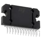
maicichuta
copilot
- Visit Flux Sign Up.
- Enter your username, email, and password. You can also sign up using your Google account.
2. Navigating the Interface- Library: Contains components that you can drag and drop onto your canvas.
- Canvas: The workspace where you'll build your schematics and PCB layouts.
- Toolbars: Options for placing components, routing, simulations, etc.
3. Placing Components- Search: Use the search bar in the library to find the components you need.
- Drag and Drop: Simply drag components from the library onto the canvas.
4. Connecting Components- Wires and Traces: Click on the pin of a component and drag to another pin to create a connection.
- For example:
- Connect
- Connect
5. SimulationR1:1toC1:1.U1:VCCtoP1:VCC,R2:2, andU2:VCC.- You can simulate your design within Flux to see how it performs. This is great for testing before actually building the hardware.
6. Positioning and Routing- Positioning: Arrange your components neatly to make the schematic easy to read.
- Routing: Use the routing tools to connect components with traces if you're planning a PCB.
7. Getting Help- If you run into any issues, there are several ways to get help:
- Flux Documentation: Access detailed guides and FAQs.
- Slack Community: Ask questions and interact with other engineers and the Flux team.
- Video Tutorials: Explore video tutorials and crash courses on YouTube or Flux’s website.
8. Act on Your Schematic