Part Information Review and Datasheet Update
Worked for 9 mins 37 sec
Reviewed the part and updated the project-level datasheet link to the official ams OSRAM PDF:
Summary:
- MPN:
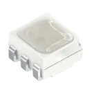
LRTBGWSR-4U4V-JW+8A8B-D8-3S4U-7Z - Manufacturer: ams OSRAM
- Family/package: OSIRE™ E3635, white PLCC-6, silicone resin, 6-SMD/J-lead RGB LED
- Ordering code:
Q65113A7820 - Channels: red, true green, blue; individually addressable
- AEC-Q102 qualified; ESD HBM Class 2, 2 kV
- Operating temperature: −40 °C to +110 °C
- Max junction temperature: 125 °C
- Forward current range/max: 5 mA to 50 mA per channel at TS = 25 °C
- Typical forward voltage at 20 mA:
- Red: 2.15 V typ, 1.90–2.50 V
- True green: 2.65 V typ, 2.10–2.90 V
- Blue: 2.85 V typ, 2.50–3.10 V
- Dominant wavelength typ:
- Red: 626 nm
- True green: 528 nm
- Blue: 465 nm
Cross-check result:
- Symbol terminals match the datasheet pin names and pin numbers:
C1Cathode True GreenA1Anode True GreenC2Cathode RedA2Anode RedC3Cathode BlueA3Anode Blue
- Footprint has 6 SMD rectangular pads matching the PLCC-6 pin count.
- Pad grouping/placement is consistent with a 3-per-side PLCC-6 layout and the schematic terminal names map correctly to the physical pad names.
Flagged issues:
- The project description says “Discrete 2.05 V Red, 2.6 V Green, 2.85 V Blue”; the official datasheet gives red VF typ as 2.15 V, not 2.05 V.
- I added
Datasheet URL,Manufacturer Name, andManufacturer Part Numberas project-level properties, but Flux warned these are non-standard project property names. The values were still set successfully. - I could not extract numeric solder-pad drawing dimensions from the PDF image content through the available text extraction, so the footprint was checked by pin count, pad naming, and topology rather than a full dimensional tolerance audit.
Fix voltage description
Audit footprint dimensions
Run part review
Add design notes
Check manufacturing fit
Name
Pin #
Type
Part Type
Pin Orientation
Terminal Order
ANODE_TRUE_GREEN
A1
Unspecified
Terminal
Left
1
ANODE_RED
A2
Unspecified
Terminal
Left
3
ANODE_BLUE
A3
Unspecified
Terminal
Left
2
CATHODE_TRUE_GREEN
C1
Unspecified
Terminal
Right
1
CATHODE_RED
C2
Unspecified
Terminal
Right
3
CATHODE_BLUE
C3
Unspecified
Terminal
Right
2
LRTBGWSR-4U4V-JW+8A8B-D8-3S4U-7Z