Relay and Lighting Setup
Thought for 1 min 43 sec
I’ll add a 5V SSD1306 I2C header and two ULN2003A input headers, with DNP 4.7k pull-ups, wired to your Nano.
- Place 4-pin Header (GND,VCC,SCL,SDA) → GND, 5V, SCL→A5, SDA→A4.
- Add two 4.7k Resistor pull-ups: A4→ 5V, A5→ 5V, mark both DNP.
- Place two 6-pin Header (IN1,IN2,IN3,IN4,VCC,GND). Header 1 IN1..IN4 → D4–D7; Header 2 IN1..IN4 → D8, D9, D10, D11/MOSI; both VCC→ 5V, GND→GND.
Click Start on the plan bar to execute.

Use D4–D7 and D8–D11 as you suggested for the ULN2003A inputs,
Thought for 1 min 23 sec
I’ll add a 5V SSD1306 I2C header and two ULN2003A input headers, with DNP 4.7k pull-ups, wired per your pin choices.
- SSD1306 4-pin header [GND, VCC, SCL, SDA] → GND, 5V, A5, A4.
- Two 4.7k Resistors as DNP pull-ups: A4→ 5V, A5→ 5V.
- ULN2003A header 1 (IN1,IN2,IN3,IN4,VCC,GND): IN1..IN4 → D4–D7; VCC→ 5V, GND→GND.
- ULN2003A header 2 (IN1,IN2,IN3,IN4,VCC,GND): IN1..IN4 → D8–D11; VCC→ 5V, GND→GND.
Click Start on the plan bar and I’ll execute these changes.
Confirm pin mapping
Ask about I2C pull-ups
Clarify header orientation
Ask about current limits
Add decoupling caps
Name
Pin #
Type
Current
Max Current
Part Type
Pin Orientation
Section
Terminal Order
D1/TX
1
Bi-Directional
0.02A
0.02A
Terminal
Left
GPIO
D0/RX
2
Bi-Directional
0.02A
0.02A
Terminal
Left
GPIO
RESET
3
Input
0.02A
0.02A
Terminal
Top
Power
COM/GND
4
Power In
0.5A
0.5A
Terminal
Right
Power
D2
5
Bi-Directional
0.02A
0.02A
Terminal
Left
GPIO
D3
6
Bi-Directional
0.02A
0.02A
Terminal
Left
GPIO
D4
7
Bi-Directional
0.02A
0.02A
Terminal
Left
GPIO
D5
8
Bi-Directional
0.02A
0.02A
Terminal
Left
GPIO
D6
9
Bi-Directional
0.02A
0.02A
Terminal
Left
GPIO
D7
10
Bi-Directional
0.02A
0.02A
Terminal
Right
GPIO
D8
11
Bi-Directional
0.02A
0.02A
Terminal
Right
GPIO
D9
12
Bi-Directional
0.02A
0.02A
Terminal
Right
GPIO
D10
13
Bi-Directional
0.02A
0.02A
Terminal
Right
GPIO
D11/MOSI
14
Bi-Directional
0.02A
0.02A
Terminal
Right
GPIO
D12/MISO
15
Bi-Directional
0.02A
0.02A
Terminal
Right
GPIO
D13/SCK
16
Bi-Directional
0.02A
0.02A
Terminal
Right
GPIO
3V3
17
Power In
0.5A
0.5A
Terminal
Top
Power
AREF
18
Input
0.02A
0.02A
Terminal
Top
Power
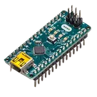
Arduino Nano