Ultrasonic Wind Sensor Design
Thought for 22 sec
122 days
Harika, elindeki STM32F103C8T6 kartı kullanarak fan aç/kapat devresinden ilerleyelim.
Bu sayfa bir parça/proje sayfası olduğu için en doğrusu bununla uyumlu yeni bir proje açmak. Senin için hazır bağlantı oluşturdum:
Bu projede tipik olarak şunlar olacak:
- STM32F103C8T6 kartı
- Bir MOSFET
- Gate direnci
- Gate pull-down direnci
- Fan konnektörü
- Gerekirse koruma diyodu
İstersen bir sonraki adımda sana ayrıca:
- 12 V fan için en doğru MOSFET’i
- Hangi STM32 pini ile sürmenin uygun olduğunu
- Basit örnek aç/kapat kodunu da hazırlayayım.

122 days
HAZIRLA
Thought for 43 sec
122 days
STM32F103C8T6 ile fan aç/kapat projesini hazırladım.
- STM32F103C8T6 geliştirme kartı eklenecek
- Fan için MOSFET sürme katı kurulacak
- Güç girişi, koruma ve programlama bağlantıları eklenecek
- Tüm bağlantılar tamamlanıp şema kontrol edilecek
Başlatmak için plan çubuğundaki Start düğmesine tıkla.
MOSFET seç
Koruma elemanları ekle
Güç girişini netleştir
list all ICs and the decoupling capacitors attached to each.
Ensure to include a...

@copilot list all ICs and the decoupling capacitors attached to each.
Ensure to include all ICs present in the design, including digital ICs, power converters, LDOs, etc.
For every IC, clearly state:
- What power net the decoupling capacitors are attached to. What is the stated voltage of that net.
- The voltage rating and value of the attached decoupling capacitors.
- Signal with the expression “[WARNING]” if any of the following conditions are met: no decoupling capacitors are attached; the voltage of the power net is higher than the voltage rating of the capacitor; No voltage range was stated for the capacitor. Give a separate “[WARNING]” for each condition. Signal with the expression “[OK]” if none of those conditions are met
- Express the result in a markdown-formatted table
2y
Given the project details provided, it seems the primary component in question is the STM32F103C8T6 microcontroller, which is an ARM Cortex-M3 series microcontroller. Based on the shared project details, there are no specific decoupling capacitors explicitly listed as attached to this IC or any other ICs, which makes it challenging to provide information regarding the power nets, voltage ratings, and values of attached decoupling capacitors.
However, I can guide you on standard practices and what would typically be expected in a well-designed circuit involving this microcontroller:
- Decoupling capacitors are vital for stabilizing power supply voltages and minimizing voltage spikes. A common approach is to attach at least one 0.1uF ceramic capacitor close to each power pin of the microcontroller for decoupling. Additional electrolytic capacitors (e.g., 10uF) might be used near the power source for bulk decoupling.
- For ICs like LDOs (Low Drop-Out regulators), power converters, and digital ICs that you might add to your project, similar decoupling practices apply: a combination of bulk and ceramic capacitors near the power pins.
Without specific capacitors and additional ICs being mentioned and without predefined electrical connections, an exact table as requested can't be provided accurately. Nevertheless, here's a guideline on what information would be necessary for a comprehensive table, assuming standard values where specifics are missing:
Table
| IC Designator | Power Net | Voltage of Net | Capacitor Value | Capacitor Voltage Rating | Status |
|---|---|---|---|---|---|
| U1 (STM32F103C8T6) | VDD, VDDA, VBAT | 3.3V (assumed) | 0.1uF (Ceramic), 10uF (Electrolytic) | 6.3V (assumed for both) | [WARNING] No decoupling capacitors attached |
Since no decoupling capacitors are listed in the provided project details, the status column includes a warning. In an actual design process, ensure:
- Each IC, including digital ICs, power converters, LDOs, etc., has decoupling capacitors attached close to its power supply pins.
- The voltage rating of the capacitors exceeds the power net voltage.
- All necessary details for the capacitors, such as their value and voltage rating, are provided.
If you have more specific components and connections in mind or if there are updates to your project, feel free to share, and I can offer more tailored guidance.
2y
Someone is typing...
8
recommend a replacement for BOOT0.

2y
BOOT0 is a specific configuration pin on the STM32F103C8T6 microcontroller. It is used to select the boot space at the startup of the microcontroller.
It's important to note that BOOT0 cannot be replaced by a simple component such as a resistor or capacitor, as it is an integral part of the microcontroller's architecture. It's a hardware feature of the STM32 series and isn't available as a separate component. If you're looking for a replacement for the whole microcontroller with similar boot configuration options, you might consider other microcontrollers in the STM32 series.
Alternatively, if you want to emulate the function of this pin externally, you might be able to employ an external memory chip and a small piece of logic or another microcontroller to manage the decision between boot sources. However, this would significantly complicate the board design.
If you're finding you need to switch the state of the BOOT0 pin frequently, it might be worth to connect it to a GPIO pin from another microcontroller or a jumper for manual control.
Please let me know what specifically you're trying to achieve so I can provide a more accurate suggestion.
2y
Someone is typing...
3
Check that none of the unconnected pins require pull-up or pull-down resistors t...

2y
To determine the need for pull-up or pull-down resistors on the unconnected pins of the STM32F103C8T6 microcontroller, let's review the common requirements for various types of pins on microcontrollers like STM32 series from STMicroelectronics. I'll base this on general practices and the typical behavior of such microcontrollers:
-
Digital I/O Pins (GPIO): Most digital I/O pins on STM32 microcontrollers are configured as floating inputs after reset. For any pin configured as an input, if it's not externally driven, it's a good practice to enable either an internal pull-up or pull-down resistor to ensure it doesn't float. This can often be done through software configuration in the microcontroller's setup code. However, for critical paths or where software configuration isn't feasible early enough in the initialization process, external resistors may be necessary.
-
Analog Pins (ADC inputs): For analog pins intended for use as ADC inputs, it's generally best not to attach pull-up or pull-down resistors, as these could affect the accuracy of the analog readings. If these pins are not used, they should be left floating or, in some designs, connected to a known stable voltage through a high-value resistor to minimize noise.
-
Reset Pin (NRST): The NRST pin is usually internally pulled up, but in noisy environments or for added reliability, an external pull-up resistor might be recommended. Additionally, a capacitor to ground could help debounce the reset signal, though this needs to be carefully sized not to interfere with the programming and reset mechanisms.
-
Oscillator Pins (OSC_IN/OSC_OUT for external crystal oscillator): If an external oscillator is not used, these pins typically don't require pull-up or pull-down resistors.
-
Boot Configuration Pins (BOOT0, BOOT1): These pins determine the boot mode of the microcontroller at startup. BOOT0 is usually pulled down for the standard boot mode from the main Flash memory. If BOOT0 or other boot configuration pins are present, they should be tied to a known state according to the desired boot configuration. For BOOT0, a pull-down is commonly used unless booting from system memory or SRAM is required.
-
Communication Interface Pins (I2C, SPI, USART, etc.): For unused communication interface pins configured as inputs or not explicitly driven by an external source, pull-up or pull-down resistors can help ensure these pins don't float, potentially leading to undesired power consumption or behavior. For I2C specifically, pull-up resistors are required for SDA and SCL lines, if these pins are used.
-
Power Pins (VDD, VSS, VBAT, VDDA, VSSA): These are power supply and ground pins and do not require pull-up or pull-down resistors. They should be properly decoupled with capacitors close to the microcontroller pins.
Given the above considerations, for your project with the STM32F103C8T6, you should review any pins configured as digital inputs without a definite external driver and consider applying pull-up or pull-down resistors as needed based on their intended function. Here are a few specific considerations:
- NRST: Consider an external pull-up if your design is subject to noise.
- BOOT0: Should be pulled low for normal operation unless you intend to use alternate boot modes.
- Digital I/O pins not used (e.g., PAx, PBx, PCx, PDx): If configured as inputs and not connected, consider setting them to a known state with pull-up or pull-down resistors.
- Analog Inputs (If any are intended for ADC use): Should generally be left floating or carefully managed if not used.
Be sure to configure these settings through software where applicable, especially for GPIO pins that can often be configured with internal pull-ups or pull-downs. Always refer to the specific part's datasheet and reference manual for detailed information on pin characteristics and recommendations.
2y
Someone is typing...
9
Reviews
 A generic fixed inductor suitable for rapid circuit topology development. The footprint automatically adapts based on the selected package, supporting standard SMD sizes (e.g., 0402, 0603, 0805) as well as well-known inductor packages such as SDR1806, PA4320, SRN6028, and SRR1260. Standard inductor values: 1.0 nH, 10 nH, 100 nH, 1.0 µH, 10 µH, 100 µH, 1.0 mH 1.2 nH, 12 nH, 120 nH, 1.2 µH, 12 µH, 120 µH, 1.2 mH 1.5 nH, 15 nH, 150 nH, 1.5 µH, 15 µH, 150 µH, 1.5 mH 1.8 nH, 18 nH, 180 nH, 1.8 µH, 18 µH, 180 µH, 1.8 mH 2.2 nH, 22 nH, 220 nH, 2.2 µH, 22 µH, 220 µH, 2.2 mH 2.7 nH, 27 nH, 270 nH, 2.7 µH, 27 µH, 270 µH, 2.7 mH 3.3 nH, 33 nH, 330 nH, 3.3 µH, 33 µH, 330 µH, 3.3 mH 3.9 nH, 39 nH, 390 nH, 3.9 µH, 39 µH, 390 µH, 3.9 mH 4.7 nH, 47 nH, 470 nH, 4.7 µH, 47 µH, 470 µH, 4.7 mH 5.6 nH, 56 nH, 560 nH, 5.6 µH, 56 µH, 560 µH, 5.6 mH 6.8 nH, 68 nH, 680 nH, 6.8 µH, 68 µH, 680 µH, 6.8 mH 8.2 nH, 82 nH, 820 nH, 8.2 µH, 82 µH, 820 µH, 8.2 mH #generics #CommonPartsLibraryjharwinbarrozo16.5k
- A generic fixed capacitor ideal for rapid circuit topology development. You can choose between polarized and non-polarized types, its symbol and the footprint will automatically adapt based on your selection. Supported options include standard SMD sizes for ceramic capacitors (e.g., 0402, 0603, 0805), SMD sizes for aluminum electrolytic capacitors, and through-hole footprints for polarized capacitors. Save precious design time by seamlessly add more information to this part (value, footprint, etc.) as it becomes available. Standard capacitor values: 1.0pF, 10pF, 100pF, 1000pF, 0.01uF, 0.1uF, 1.0uF, 10uF, 100uF, 1000uF, 10000uF 1.1pF, 11pF, 110pF, 1100pF 1.2pF, 12pF, 120pF, 1200pF 1.3pF, 13pF, 130pF, 1300pF 1.5pF, 15pF, 150pF, 1500pF, 0.015uF, 0.15uF, 1.5uF, 15uF, 150uF, 1500uF 1.6pF, 16pF, 160pF, 1600pF 1.8pF, 18pF, 180pF, 1800pF 2.0pF, 20pF, 200pF, 2000pF 2.2pF, 22pF, 220pF, 2200pF, 0.022uF, 0.22uF, 2.2uF, 22uF, 220uF, 2200uF 2.4pF, 24pF, 240pF, 2400pF 2.7pF, 27pF, 270pF, 2700pF 3.0pF, 30pF, 300pF, 3000pF 3.3pF, 33pF, 330pF, 3300pF, 0.033uF, 0.33uF, 3.3uF, 33uF, 330uF, 3300uF 3.6pF, 36pF, 360pF, 3600pF 3.9pF, 39pF, 390pF, 3900pF 4.3pF, 43pF, 430pF, 4300pF 4.7pF, 47pF, 470pF, 4700pF, 0.047uF, 0.47uF, 4.7uF, 47uF, 470uF, 4700uF 5.1pF, 51pF, 510pF, 5100pF 5.6pF, 56pF, 560pF, 5600pF 6.2pF, 62pF, 620pF, 6200pF 6.8pF, 68pF, 680pF, 6800pF, 0.068uF, 0.68uF, 6.8uF, 68uF, 680uF, 6800uF 7.5pF, 75pF, 750pF, 7500pF 8.2pF, 82pF, 820pF, 8200pF 9.1pF, 91pF, 910pF, 9100pF #generics #CommonPartsLibraryjharwinbarrozo1.5M
- A generic fixed resistor ideal for rapid circuit topology development. Its footprint automatically adapts based on the selected package case code—supporting 0402, 0603, 0805, 1203, and many other standard SMD packages, as well as axial horizontal and vertical configurations. Save precious design time by seamlessly add more information to this part (value, footprint, etc.) as it becomes available. Standard resistor values: 1.0 ohm, 10 ohm, 100 ohm, 1.0k ohm, 10k ohm, 100k ohm, 1.0M ohm 1.1 ohm, 11 ohm, 110 ohm, 1.1k ohm, 11k ohm, 110k ohm, 1.1M ohm 1.2 ohm, 12 ohm, 120 ohm, 1.2k ohm, 12k ohm, 120k ohm, 1.2M ohm 1.3 ohm, 13 ohm, 130 ohm, 1.3k ohm, 13k ohm, 130k ohm, 1.3M ohm 1.5 ohm, 15 ohm, 150 ohm, 1.5k ohm, 15k ohm, 150k ohm, 1.5M ohm 1.6 ohm, 16 ohm, 160 ohm, 1.6k ohm, 16k ohm, 160k ohm, 1.6M ohm 1.8 ohm, 18 ohm, 180 ohm, 1.8K ohm, 18k ohm, 180k ohm, 1.8M ohm 2.0 ohm, 20 ohm, 200 ohm, 2.0k ohm, 20k ohm, 200k ohm, 2.0M ohm 2.2 ohm, 22 ohm, 220 ohm, 2.2k ohm, 22k ohm, 220k ohm, 2.2M ohm 2.4 ohm, 24 ohm, 240 ohm, 2.4k ohm, 24k ohm, 240k ohm, 2.4M ohm 2.7 ohm, 27 ohm, 270 ohm, 2.7k ohm, 27k ohm, 270k ohm, 2.7M ohm 3.0 ohm, 30 ohm, 300 ohm, 3.0K ohm, 30K ohm, 300K ohm, 3.0M ohm 3.3 ohm, 33 ohm, 330 ohm, 3.3k ohm, 33k ohm, 330k ohm, 3.3M ohm 3.6 ohm, 36 ohm, 360 ohm, 3.6k ohm, 36k ohm, 360k ohm, 3.6M ohm 3.9 ohm, 39 ohm, 390 ohm, 3.9k ohm, 39k ohm, 390k ohm, 3.9M ohm 4.3 ohm, 43 ohm, 430 ohm, 4.3k ohm, 43K ohm, 430K ohm, 4.3M ohm 4.7 ohm, 47 ohm, 470 ohm, 4.7k ohm, 47k ohm, 470k ohm, 4.7M ohm 5.1 ohm, 51 ohm, 510 ohm, 5.1k ohm, 51k ohm, 510k ohm, 5.1M ohm 5.6 ohm, 56 ohm, 560 ohm, 5.6k ohm, 56k ohm, 560k ohm, 5.6M ohm 6.2 ohm, 62 ohm, 620 ohm, 6.2k ohm, 62K ohm, 620K ohm, 6.2M ohm 6.8 ohm, 68 ohm, 680 ohm, 6.8k ohm, 68k ohm, 680k ohm, 6.8M ohm 7.5 ohm, 75 ohm, 750 ohm, 7.5k ohm, 75k ohm, 750k ohm, 7.5M ohm 8.2 ohm, 82 ohm, 820 ohm, 8.2k ohm, 82k ohm, 820k ohm, 8.2M ohm 9.1 ohm, 91 ohm, 910 ohm, 9.1k ohm, 91k ohm, 910k ohm, 9.1M ohm #generics #CommonPartsLibraryjharwinbarrozo1.5M
- An electrical connector acting as reusable interface to a conductor and creating a point where external circuits can be connected.Terminal
- Wirelessly connects nets on schematic. Used to organize schematics and separate functional blocks. To wirelessly connect net portals, give them same designator. #portaljharwinbarrozo43.0M
- General Purpose Thick Film Standard Power and High-Power Chip Resistor 47 kOhms ±5% 0.125W, 1/8W Chip Resistor 0805 (2012 Metric) Automotive AEC-Q200 Thick Film Features: - RMCF – standard power ratings - RMCP – high power ratings - Nickel barrier terminations standard - Power derating from 100% at 70ºC to zero at +155ºC - RoHS compliant, REACH compliant, and halogen free - AEC-Q200 compliantjharwinbarrozo1.2M
- 10 µF 16 V Aluminum - Polymer Capacitors Radial, Can - SMD 30mOhm 2000 Hrs @ 105°C #commonpartslibrary #capacitor #aluminumpolymer #radialcanjharwinbarrozo1.2M
- Battery Holder (Open) Coin, 20.0mm 1 Cell SMD (SMT) Tab bate or batt #forLedBlinkjharwinbarrozo700.5k


STM32F103C8T6
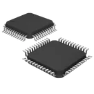
ARM® Cortex®-M3 series Microcontroller IC 32-Bit 72MHz 64KB (64K x 8) FLASH #microcontrollers #stm32 #commonpartslibrary
Properties
Microcontroller
STMicroelectronics
STM32F103C8T6
U
Parametric
Pricing & Availability
Distributor | Qty 1 |
|---|
Controls
Welcome 👋
Flux accelerates your PCB design with AI.
Create your account to start using this component and bring your ideas to life.
zyra
copilot
Table