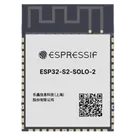
Pin Classification Overview
Worked for 1 min 41 sec
I checked the Espressif datasheet for this module. Here are the pin groups you asked for:
Bootstrap / strapping pins
These pins are sampled at reset, then can be used as normal GPIO afterward.
Table
| Module pin | Pin name | Reset role | Default strap |
|---|---|---|---|
| 16 | IO46 | Boot mode select with IO0, ROM message printing control | Weak pull-down |
| 26 | IO45 | VDD_SPI voltage select | Weak pull-down |
| 27 | IO0 | Boot mode select with IO46 | Weak pull-up |
Table
| IO0 | IO46 | Result |
|---|---|---|
| 1 | any | SPI boot |
| 0 | 0 | Joint download boot |
| 0 | 1 | Invalid combination, avoid |
Table
| Module pin | Pin name | Notes |
|---|---|---|
| 16 | IO46 | Input-only pin, fixed pull-down, also a strapping pin |
That is the only input-only GPIO called out here.
Pins connected to internal memory / reserved by flash interface
These are the ones you should treat as memory-related or restricted.
Strongly reserved / not recommended for other use
These correspond to the SPI0/1 interface used for in-package flash, or recommended for flash/PSRAM connection.
Table
| Chip GPIO | Module pin exposure | Module pin name |
|---|---|---|
| GPIO26 | not exposed as GPIO26 label on module | not broken out directly |
| GPIO27 | not exposed as GPIO27 label on module | not broken out directly |
| GPIO28 | not exposed as GPIO28 label on module | not broken out directly |
| GPIO29 | not exposed as GPIO29 label on module | not broken out directly |
| GPIO30 | not exposed as GPIO30 label on module | not broken out directly |
| GPIO31 | not exposed as GPIO31 label on module | not broken out directly |
| GPIO32 | not exposed as GPIO32 label on module | not broken out directly |
These are associated with higher SPI flash/PSRAM data lines or DQS, so use caution.
Table
| Module pin | Pin name | Memory-related function in datasheet |
|---|---|---|
| 24 | IO33 | SPIIO4 / FSPIHD |
| 25 | IO34 | SPIIO5 / FSPICS0 |
| 28 | IO35 | SPIIO6 / FSPID |
| 29 | IO36 | SPIIO7 / FSPICLK |
| 30 | IO37 | SPIDQS / FSPIQ |
- Definitely memory-reserved / avoid: GPIO26 to GPIO32
- Memory-related / use with caution: IO33 to IO37
- Normal GPIO from your requested categories: the rest, except the special-case pins above
Table
| Module pin | Pin name | USB function |
|---|---|---|
| 13 | IO19 | USB_D- |
| 14 | IO20 | USB_D+ |
- Bootstrap pins: IO0, IO45, IO46
- Input-only pins: IO46
- Internal-memory / flash-related pins: GPIO26 to GPIO32 reserved, and IO33 to IO37 are memory-bus related / caution
- USB pins: IO19 = USB_D-, IO20 = USB_D+
If you want, I can turn this into a pin classification table for all 41 pins next.
Use ESP32 datasheet
Flag restricted pins
Save pin notes
Name
Pin #
Type
Part Type
Pin Orientation
Section
Terminal Order
Terminal Type
GND
1
Unspecified
Terminal
Right
GND
10
powerIn
3V3
2
Unspecified
Terminal
Top
POWER
1
powerIn
EN
3
Unspecified
Terminal
Left
PROGRAMMING
2
INPUT
IO4
4
Unspecified
Terminal
Left
GPIO
6
bidi
IO5
5
Unspecified
Terminal
Left
GPIO
6
bidi
IO6
6
Unspecified
Terminal
Left
GPIO
6
bidi
IO7
7
Unspecified
Terminal
Left
GPIO
6
bidi
IO15
8
Unspecified
Terminal
Right
GPIO
6
bidi
IO16
9
Unspecified
Terminal
Right
GPIO
6
bidi
IO17
10
Unspecified
Terminal
Right
GPIO
6
bidi
IO18
11
Unspecified
Terminal
Right
GPIO
6
bidi
IO8
12
Unspecified
Terminal
Left
GPIO
6
bidi
IO19
13
Unspecified
Terminal
Left
USB
4
bidi
IO20
14
Unspecified
Terminal
Left
USB
4
bidi
IO3
15
Unspecified
Terminal
Left
GPIO
6
bidi
IO46
16
Unspecified
Terminal
Right
BOOTSTRAP
3
INPUT
IO9
17
Unspecified
Terminal
Left
GPIO
6
bidi
IO10
18
Unspecified
Terminal
Left
GPIO
6
bidi
ESP32-S2-SOLO-2