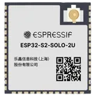
Component Pin Classification
Thought for 1 min 25 sec
From the Espressif datasheet for this module, here are the pin groups you asked for:
Bootstrap pins
These are the module strapping pins used at reset:
- IO0 - module pin 27
- IO45 - module pin 26
- IO46 - module pin 16
What they control:
- IO0 + IO46: boot mode
- IO45: VDD_SPI voltage selection
- IO46: ROM message printing
- IO46 - module pin 16 - type I
That is the only pin in the module pin table marked input-only.
USB pins
- IO19 - module pin 13 - USB_D-
- IO20 - module pin 14 - USB_D+
There are two useful interpretations here:
These pins are labeled with FSPI/SPIIO functions in the module pin table:
- IO9 - pin 17 - FSPIHD
- IO10 - pin 18 - FSPICS0 / FSPIIO4
- IO11 - pin 19 - FSPID / FSPIIO5
- IO12 - pin 20 - FSPICLK / FSPIIO6
- IO13 - pin 21 - FSPIQ / FSPIIO7
- IO14 - pin 22 - FSPIWP / FSPIDQS
- IO33 - pin 24 - SPIIO4 / FSPIHD
- IO34 - pin 25 - SPIIO5 / FSPICS0
- IO35 - pin 28 - SPIIO6 / FSPID
- IO36 - pin 29 - SPIIO7 / FSPICLK
- IO37 - pin 30 - SPIDQS / FSPIQ
- IO38 - pin 31 - FSPIWP
The ESP32-S2 chip datasheet says the pins allocated for communication with in-package flash/PSRAM should not be used for other purposes. On the chip, these are the dedicated SPI memory pins such as:
- SPICS0
- SPIHD
- SPIWP
- SPICLK
- SPIQ
- SPID
- and, for wider memory modes, GPIO33-GPIO37
On the module, the always-reserved internal flash connections are generally internalized rather than simply exposed as ordinary user pins, so if your goal is a safe "do not use casually" list, the cautious exposed-pin set is:
Table
| Category | Pins |
|---|---|
| Definitely strapping-sensitive | IO0, IO45, IO46 |
| USB-fixed by default | IO19, IO20 |
| Memory-related / use with caution | IO33, IO34, IO35, IO36, IO37 |
| Memory-bus alt-function pins also shown in pin table | IO9, IO10, IO11, IO12, IO13, IO14, IO38 |
If you want, I can also turn this into a clean Flux terminal classification table with columns like Pin Name / Pin Number / Pin Type / Section / Pin Group / Notes for your part project.
List EPAD pin groups
Include exact pin names
Make a pin table
Name
Pin #
Type
Part Type
Pin Orientation
Section
Terminal Order
Terminal Type
GND
1
Unspecified
Terminal
Right
GND
10
powerIn
3V3
2
Unspecified
Terminal
Top
POWER
1
powerIn
EN
3
Unspecified
Terminal
Left
PROGRAMMING
2
INPUT
IO4
4
Unspecified
Terminal
Left
GPIO
7
bidi
IO5
5
Unspecified
Terminal
Left
GPIO
7
bidi
IO6
6
Unspecified
Terminal
Left
GPIO
7
bidi
IO7
7
Unspecified
Terminal
Left
GPIO
7
bidi
IO15
8
Unspecified
Terminal
Right
GPIO
7
bidi
IO16
9
Unspecified
Terminal
Right
GPIO
7
bidi
IO17
10
Unspecified
Terminal
Right
GPIO
7
bidi
IO18
11
Unspecified
Terminal
Right
GPIO
7
bidi
IO8
12
Unspecified
Terminal
Left
GPIO
7
bidi
IO19
13
Unspecified
Terminal
Left
USB
4
bidi
IO20
14
Unspecified
Terminal
Left
USB
4
bidi
IO3
15
Unspecified
Terminal
Left
GPIO
7
bidi
IO46
16
Unspecified
Terminal
Right
BOOTSTRAP
3
INPUT
IO9
17
Unspecified
Terminal
Left
GPIO
7
bidi
IO10
18
Unspecified
Terminal
Left
GPIO
7
bidi
ESP32-S2-SOLO-2U