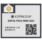
Component Pin Classification
Thought for 58 sec
I checked the Espressif datasheet for ESP32-PICO-MINI-02U. Here are the pin groups you asked for:
Bootstrap / strapping pins
These are sampled at reset for boot configuration:
Table
| Module Pin | Signal | Notes |
|---|---|---|
| 19 | IO12 / MTDI | Strapping pin, also affects VDD_SDIO voltage |
| 21 | IO15 / MTDO | Strapping pin, also affects boot log output |
| 22 | IO2 | Strapping pin |
| 23 | IO0 | Strapping pin, boot/download mode control |
| 29 | IO5 | Strapping pin |
These pins are input-only, not bidirectional GPIO:
Table
| Module Pin | Signal | Functions |
|---|---|---|
| 4 | I36 / GPIO36 | ADC1_CH0, RTC_GPIO0 |
| 5 | I37 / GPIO37 | ADC1_CH1, RTC_GPIO1 |
| 6 | I38 / GPIO38 | ADC1_CH2, RTC_GPIO2 |
| 7 | I39 / GPIO39 | ADC1_CH3, RTC_GPIO3 |
| 9 | I34 / GPIO34 | ADC1_CH6, RTC_GPIO4 |
| 10 | I35 / GPIO35 | ADC1_CH7, RTC_GPIO5 |
| 8 | EN | Chip enable input only |
The module datasheet says some chip pins are used internally and are not led out on the module, while others are brought out but are tied to in-package flash/PSRAM and are not recommended for other use.
Not led out on the module
Table
| Chip Signal | Internal Use |
|---|---|
| CMD / IO11 | Embedded flash |
| CLK / IO6 | Embedded flash |
| SD2 / IO9 | Embedded PSRAM |
| SD3 / IO10 | Embedded PSRAM |
Table
| Module Pin | Signal | Internal Connection |
|---|---|---|
| 27 | IO7 | HS1_DATA0 / flash-related bus |
| 28 | IO8 | HS1_DATA1 / flash-related bus |
| 30 | RXD0 / GPIO3 | Not internal memory |
| 31 | TXD0 / GPIO1 | Not internal memory |
More specifically from the module schematic, these internal memory-related connections are:
- IO23 -> SPIDI
- IO18 -> SPIWP
- CLK -> FLASH_CLK
- CMD -> FLASH_CS
- SD3 -> PSRAM_CLK
- SD2 -> PSRAM_CS
- IO17 -> SPIDO
- IO16 -> SPIHD
So for practical pin-classification in your part:
- Definitely internal-memory reserved / not for general use:
IO6,IO9,IO10,IO11 - Also involved in the internal flash/PSRAM interface in the module schematic:
IO16,IO17,IO18,IO23
This module does not have native USB data pins exposed in the datasheet pin table.
- No
USB_DP - No
USB_DM - No native USB interface pins listed
So the USB pins list is empty for this part.
Short summary
Table
| Category | Pins |
|---|---|
| Bootstrap pins | IO0, IO2, IO5, IO12, IO15 |
| Input-only pins | GPIO34, GPIO35, GPIO36, GPIO37, GPIO38, GPIO39, plus EN as input |
| Internal-memory connected / reserved | IO6, IO9, IO10, IO11; also module memory interface uses IO16, IO17, IO18, IO23 |
| USB pins | None |
If you want, I can turn this into a pin classification table for all 53 pins next.
Use this datasheet
Extract exact pin lists
Flag unavailable groups
Name
Pin #
Type
Part Type
Pin Orientation
Section
Terminal Order
Terminal Type
GND
1
Unspecified
Terminal
Left
GND
10
powerIn
GND
2
Unspecified
Terminal
Bottom
GND
10
powerIn
3V3
3
Unspecified
Terminal
Top
POWER
1
powerIn
I36
4
Unspecified
Terminal
Left
INPUT ONLY
4
INPUT
I37
5
Unspecified
Terminal
Right
INPUT ONLY
4
INPUT
I38
6
Unspecified
Terminal
Right
INPUT ONLY
4
INPUT
I39
7
Unspecified
Terminal
Right
INPUT ONLY
4
INPUT
EN
8
Unspecified
Terminal
Left
PROGRAMMING
2
INPUT
I34
9
Unspecified
Terminal
Left
INPUT ONLY
4
INPUT
I35
10
Unspecified
Terminal
Left
INPUT ONLY
4
INPUT
GND
11
Unspecified
Terminal
Right
GND
10
powerIn
IO32
12
Unspecified
Terminal
Right
GPIO
6
bidi
IO33
13
Unspecified
Terminal
Right
GPIO
6
bidi
GND
14
Unspecified
Terminal
Right
GND
10
powerIn
IO25
15
Unspecified
Terminal
Right
GPIO
6
bidi
IO26
16
Unspecified
Terminal
Right
GPIO
6
bidi
IO27
17
Unspecified
Terminal
Right
GPIO
6
bidi
IO14
18
Unspecified
Terminal
Left
GPIO
6
bidi
ESP32-PICO-MINI-02U