PCB Design Basics

So was I supposed to delete everything in Tacoma_dial_exhaust_test.INO and replace it with the new one sent
Thought for 22 sec
Yes. Replace everything in
Tacoma_Dial_Exhaust_Test.ino with the new artwork-based firmware.- Open the
.inotab. - Press Ctrl+A, then Delete.
- Copy the complete revised
.inocode from Firmware Starter. - Paste it into the empty
.inotab. - Add a second tab using the small dropdown/three-dot menu near the sketch tabs.
- Name the second tab exactly:
Text
ui_assets.h
- Copy the complete asset-header code from the document into that tab.
- Confirm the
.inobegins with:
Cpp
#include <Arduino.h> #include <M5Dial.h> #include "ui_assets.h"
- Click Verify, then Upload.
Do not paste the new code below the old code—it must completely replace it.
Replace file contents
Check asset tab
Use embedded art
PC817 Channel Verification
Scope
This note verifies one exhaust-remote optocoupler channel only. It does not yet approve the Joying SWC interface, vehicle power input, or permanent remote power supply.
Circuit Under Test
Diagram
The output-side 10.11 kohm pull-up is the user's verified bench-test resistor. It is a useful test load, but it is not assumed to equal the unknown internal resistance of the real Valvetronic remote.
Datasheet Basis
Sharp PC817-series data used for the conservative model:
- CTR: 50% minimum to 600% maximum at IF = 5 mA and VCE = 5 V.
- LED forward voltage: 1.2 V typical, 1.4 V maximum at IF = 20 mA; the forward-current graph indicates approximately 1.1 V near 5 mA at room temperature.
- VCE(sat): 0.1 V typical, 0.2 V maximum at IF = 20 mA and IC = 1 mA.
- Absolute maximum collector current: 50 mA.
- Absolute maximum collector-emitter voltage: 35 V.
The actual PC817C parts may have a higher CTR bin, but the simulation intentionally used the generic 50% minimum for margin.
Input Resistor Check
Using the observed approximately 1.1 V LED drop:
IF = (3.3 V - 1.1 V) / 470 ohm = 4.68 mAUsing 1.4 V as a deliberately conservative forward-drop bound:
IF = (3.3 V - 1.4 V) / 470 ohm = 4.04 mATherefore 470 ohms produces approximately 4.0 to 4.7 mA. This is appropriate for testing and close to the PC817's 5 mA CTR characterization point. It also matches the user's earlier observation of about 1.6 V across 470 ohms from a weak approximately 2.7 V coin cell:
1.6 V / 470 ohm = 3.4 mA.Conservative Collector-Current Margin
At minimum CTR = 50%:
- With IF = 4.68 mA, available collector-current capability is approximately 2.34 mA.
- With IF = 4.04 mA, available collector-current capability is approximately 2.02 mA.
The 3.27 V / 10.11 kohm pull-up test requires only approximately 0.32 mA before saturation, so the conservative available-current margin is greater than 6x.
Simulation Results
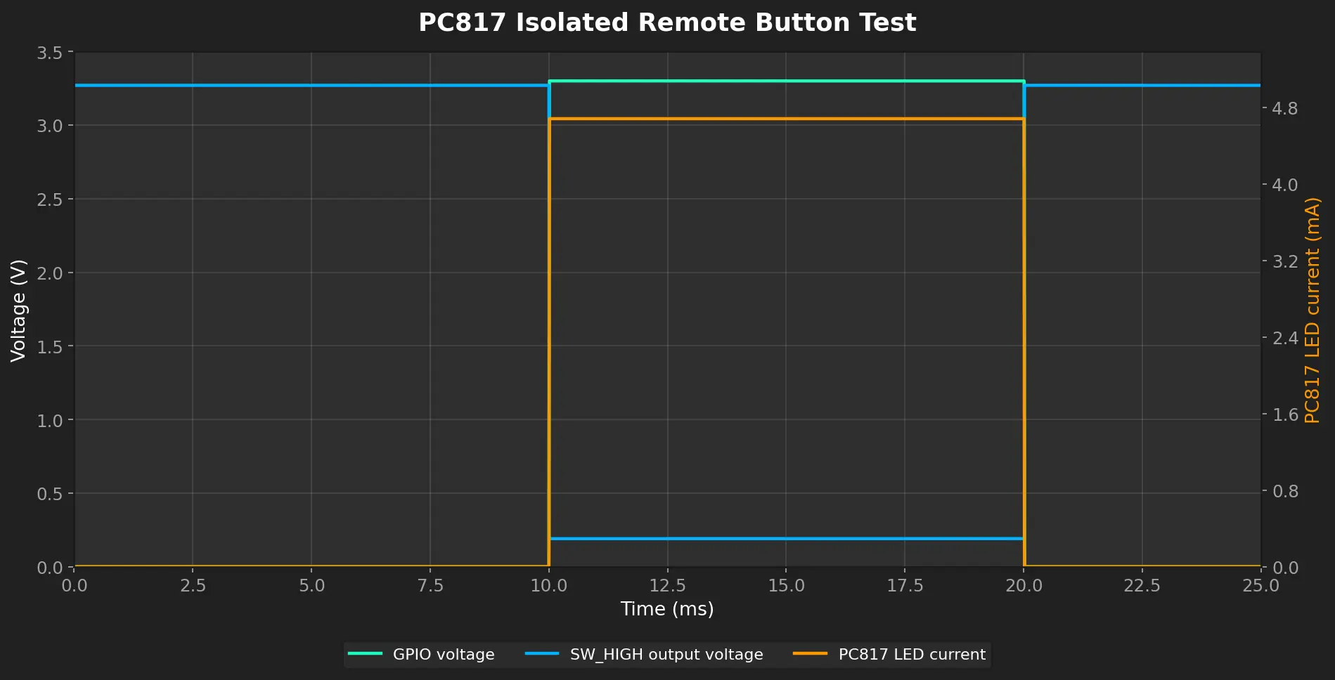
The simulation used a 3.3 V GPIO, 470 ohm input resistor, approximately 1.1 V LED at 4.68 mA, 50% CTR, a 3.27 V isolated supply, 10.11 kohm pull-up, and approximately 0.2 V worst-case saturation behavior.
Table
| Measurement | Input OFF | Input ON |
|---|---|---|
| GPIO voltage | 0 V | 3.3 V |
| PC817 LED current | approximately 0 mA | 4.681 mA |
| Voltage across 470 ohm resistor | approximately 0 V | 2.200 V |
| LED forward voltage, pins 1 to 2 | approximately 0 V | 1.100 V |
| Output collector current | approximately 0 mA | 0.305 mA |
| Output voltage, pin 4 relative to pin 3 | 3.270 V | 0.191 V |
Image
The PC817 easily pulls the 10.11 kohm test node low in the conservative model. The simulated approximately 0.19 V low is consistent with treating the device as a closed button for this test network.
Clean Breadboard Test Procedure
Perform this test with the remote still disconnected.
Wiring
- Place one PC817 across the breadboard center gap and identify the dot at pin 1.
- Connect the 3.3 V control source through 470 ohms to pin 1.
- Connect pin 2 to the control-source ground.
- Keep the output electrically separate: connect pin 3 to the CR2032 negative terminal.
- Connect the CR2032 positive terminal through the measured 10.11 kohm resistor to pin 4.
- Do not join the control-source ground to the CR2032 negative terminal.
Input OFF Measurements
Set the meter to DC volts.
- LED voltage: red probe on pin 1, black probe on pin 2. Expect approximately 0 V if the GPIO/control source is at 0 V.
- Resistor voltage: red probe on the GPIO side of 470 ohms, black probe on the pin-1 side. Expect approximately 0 V.
- Output voltage: red probe on pin 4, black probe on pin 3. Expect approximately the actual battery voltage, such as 2.7 V for the weak cell or about 3.0 to 3.3 V for a fresh source.
Input ON Measurements
Apply a verified 3.3 V control level.
- LED voltage: red probe on pin 1, black probe on pin 2. Expect roughly 1.0 to 1.3 V at room temperature.
- Resistor voltage: red probe on the GPIO side of 470 ohms, black probe on pin 1. Expect roughly 2.0 to 2.3 V.
- Input current without moving wires into current mode: calculate
measured resistor voltage / 470 ohms; expect roughly 4 to 5 mA. - Output voltage: red probe on pin 4, black probe on pin 3. Expect a low voltage, typically under approximately 0.3 V for this 10.11 kohm test load.
Safety and Troubleshooting
- Do not use the meter's current mode across a voltage source or across the optocoupler output; this creates a short circuit.
- If pin 4 remains near battery voltage while the LED measurements are correct, first verify the PC817 orientation and confirm pin 4 is on the pull-up side and pin 3 is on battery negative.
- If pin 4 and pin 3 were reversed, the phototransistor can conduct very poorly even though the input LED is working.
- A weak CR2032 is still adequate for this 10.11 kohm test because the load is only a few tenths of a milliamp, but record its voltage both before and during the ON test.
- Do not connect the PC817 output to the real remote until the spare remote is paired and the clean isolated test passes.
What This Proves and Does Not Prove
Proven for the 10.11 kohm test network:
- The 470 ohm input resistor gives suitable LED current from a 3.3 V GPIO.
- A conservatively modeled PC817 can pull a 3.27 V, 10.11 kohm output node low with strong margin.
- The collector-to-high-side and emitter-to-low-side orientation is correct for the measured remote polarity.
Still to verify on hardware:
- The real remote's current through S1 and S2 when pressed.
- The actual low-voltage threshold accepted by the remote IC.
- Both physical PC817 channels and all breadboard connections.
- The M5Stack Dial's exact accessible GPIO pins and their boot-time behavior.
Next Measurement Before Connecting the Remote
After pairing the spare remote, measure the current through one button path without placing the meter directly across the battery. The preferred low-risk method is to insert a known small resistor temporarily in series with the button path and measure its voltage drop; the exact procedure and resistor value will be selected after clear photos of the paired remote PCB and accessible switch pads are available.
Scope
Circuit Under Test
Datasheet Basis
Input Resistor Check
Conservative Collector-Current Margin
Simulation Results
Clean Breadboard Test Procedure
Wiring
Input OFF Measurements
Input ON Measurements
Safety and Troubleshooting
What This Proves and Does Not Prove
Next Measurement Before Connecting the Remote