Switches
A switch is a device that allows electricity to flow through a circuit by completing or interrupting the connection. It is a common component in electrical and electronic systems and is used in a variety of applications, such as controlling the flow of electricity in a circuit, turning devices on and off, and routing electrical signals. One of the primary use cases for switches is to control the flow of electricity in a circuit. This can be done by manually flipping the switch or by using a control mechanism, such as a timer or a sensor. Another common use for switches is to turn devices on and off. This can be done using a switch that is built into the device or by using a separate switch that is connected to the device. In addition to these basic use cases, switches can also be used to route electrical signals. For example, a switch can be used to route a signal from one device to another or to direct a signal to a specific circuit or component. If you're looking for a wide variety of switches for your projects, flux.ai has the world's largest community-driven public library of them. The library includes footprints, symbols, datasheets, and simulation models for a wide range of switches, making it easy to find the right switch for your needs.
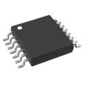
LM5010MHX/NOPB
Buck Switching Regulator IC Positive Adjustable 2.5V 1 Output 1A 14-PowerTSSOP (0.173", 4.40mm Width) The LM5010 step-down switching regulator features all the functions needed to implement a low-cost, efficient, buck bias regulator capable of supplying in excess of 1-A load current. This high-voltage regulator contains an N-Channel Buck Switch, and is available in thermally enhanced 10-pin WSON and 14-pin HTSSOP packages. The hysteretic regulation scheme requires no loop compensation, resulting in fast load transient response, and simplifies circuit implementation. The operating frequency remains constant with line and load variations due to the inverse relationship between the input voltage and the ON-time. The valley current limit detection is set at 1.25 A. Additional features include: VCC undervoltage lockout, thermal shutdown, gate drive undervoltage lockout, and maximum duty cycle limiter Features 1• Input Voltage Range: 8 V to 75 V • Valley Current Limit At 1.25 A • Switching Frequency Can Exceed 1 MHz • Integrated N-Channel Buck Switch • Integrated Start-Up Regulator • No Loop Compensation Required • Ultra-Fast Transient Response • Operating Frequency Remains Constant With Load and Line Variations • Maximum Duty Cycle Limited During Start-Up • Adjustable Output Voltage • Precision 2.5-V Feedback Reference • Thermal Shutdown • Exposed Thermal Pad for Improved Heat Dissipation 2 Applications • High Efficiency Point-of-Load (POL) Regulator • Non-Isolated Telecommunications Buck Regulator • Secondary High Voltage Post Regulator • Automotive Systems #TexasInstruments #LM5010MHXNOPB #BuckRegulator #DCDCConverter #SwitchingRegulator #PowerManagement #HighVoltage #StepDownConverter #IndustrialElectronics #EmbeddedSystems #PowerSupplyDesign #HTSSOP14 #PMIC #ElectronicsDesign #VoltageRegulator
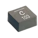
14 Uses0 StarsXAL1010-103MED
10 µH Shielded Molded Inductor 15.5 A 14.75mOhm Max Nonstandard The XAL1010-103MED specification defines the engineering requirements for a shielded power inductor designed for high-efficiency energy storage and power conversion applications. This specification establishes the functional, electrical, mechanical, thermal, environmental, and quality requirements necessary to ensure stable inductance characteristics, efficient current handling, and long-term operational reliability in power electronic systems. The component is intended for use in DC-DC converters, voltage regulators, power management circuits, industrial control equipment, automotive electronics, and embedded systems requiring compact, high-current inductive components. The magnetically shielded construction minimizes electromagnetic interference while supporting efficient energy transfer and stable performance in high-frequency switching applications. Engineering Requirements The power inductor shall be manufactured using high-quality magnetic core materials and precision-wound conductors to ensure consistent inductance, low core losses, and reliable current-carrying capability. The construction shall maintain stable electrical performance under specified operating voltage, current, frequency, and temperature conditions. Electrical characteristics shall provide accurate inductance values, low direct current resistance, high saturation current capability, and low electromagnetic emissions. The component shall maintain stable performance during continuous operation, transient loading, and thermal cycling without significant degradation of inductance or efficiency. Thermal performance shall support effective heat dissipation and continuous operation within the specified temperature range while maintaining structural integrity and electrical characteristics. The shielded construction shall minimize magnetic field leakage and improve electromagnetic compatibility within densely populated electronic assemblies. Mechanical construction shall be suitable for surface-mount assembly and compatible with automated manufacturing processes. The component shall withstand solder reflow, vibration, mechanical shock, and handling without deformation or degradation of electrical performance. Workmanship shall be free from defects including cracks, contamination, core damage, winding irregularities, or structural inconsistencies. Inspection, validation, and testing shall be conducted using calibrated equipment and controlled quality procedures to verify compliance with all applicable engineering and manufacturing requirements. Any deviation from this specification shall require formal engineering evaluation, documented technical justification, and approval through the established engineering change control process. Documentation Supporting documentation shall include engineering drawings, electrical specifications, magnetic characterization data, thermal performance reports, qualification records, inspection reports, material declarations, and revision-controlled manufacturing documentation. All documentation shall be maintained under formal configuration management and quality assurance systems to ensure complete product traceability. Revision Control Any modification to this specification shall be managed through the formal engineering change management process. All revisions shall undergo technical review, validation, and approval before implementation to ensure continued compliance with design intent and applicable engineering standards. #EngineeringSpecification #PowerInductor #ShieldedInductor #PowerElectronics #DCDCConverter #PowerManagement #Magnetics #IndustrialElectronics #QualityAssurance #EngineeringDocumentation #CommonPartsLibrary #Inductor #XAL1010
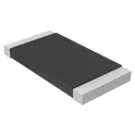
0 Uses0 StarsCRM2512-FX-1R00ELF
1 Ohms ±1% 2W Chip Resistor 2512 (6332 Metric) Current Sense Thick Film The CRM2512-FX-1R00ELF specification defines the engineering requirements for a surface-mount current sense resistor designed for precision current measurement and power management applications. This specification establishes the functional, electrical, mechanical, thermal, environmental, and quality requirements necessary to ensure accurate resistance performance, efficient power dissipation, and long-term operational reliability in electronic systems. The component is intended for use in power supplies, battery management systems, motor control circuits, industrial automation equipment, and embedded electronic applications requiring precise current monitoring. The resistor provides a low-resistance element for current sensing while maintaining high measurement accuracy, thermal stability, and compatibility with automated surface-mount manufacturing processes. Engineering Requirements The resistor shall be manufactured using high-quality resistive materials and controlled fabrication processes to ensure stable resistance characteristics, low temperature coefficient, and reliable long-term performance. The construction shall provide consistent electrical behavior throughout the specified operating conditions without significant drift or degradation. Electrical characteristics shall ensure accurate resistance value, stable current sensing performance, and low inductance suitable for high-frequency switching environments. The component shall maintain its specified tolerance and thermal performance under continuous rated power and transient load conditions. Thermal performance shall support efficient heat dissipation through the package structure and printed circuit board interface. The resistor shall withstand normal solder reflow processes and maintain structural integrity during thermal cycling, vibration, and mechanical handling. Mechanical construction shall be compatible with standard surface-mount assembly processes and shall provide reliable solder joint formation. Workmanship shall be free from defects including cracks, delamination, contamination, plating irregularities, or structural inconsistencies that could adversely affect electrical or mechanical performance. Inspection, validation, and testing shall be conducted using calibrated equipment and controlled quality procedures to verify compliance with all applicable engineering and manufacturing requirements. Any deviation from this specification shall require formal engineering evaluation, documented technical justification, and approval through the established engineering change control process. Documentation Supporting documentation shall include engineering drawings, electrical performance specifications, thermal characterization data, qualification reports, inspection records, material declarations, and revision-controlled manufacturing documentation. All documentation shall be maintained under formal configuration management and quality assurance systems to ensure complete product traceability. Revision Control Any modification to this specification shall be managed through the formal engineering change management process. All revisions shall undergo technical review, validation, and approval before implementation to ensure continued compliance with design intent and applicable engineering standards. #EngineeringSpecification #CurrentSenseResistor #PowerElectronics #SurfaceMount #PrecisionResistor #IndustrialElectronics #PowerManagement #QualityAssurance #EngineeringDocumentation #ElectronicComponents
0 Uses0 StarsG6K-2F-Y DC5
Telecom Relay DPDT (2 Form C) Surface Mount The G6K-2F-Y DC5 specification defines the engineering requirements for a low-profile dual-pole signal relay designed for precision switching in electronic control and communication systems. This specification establishes the functional, electrical, mechanical, environmental, and quality requirements necessary to ensure reliable signal switching, low contact resistance, and long-term operational stability in compact electronic assemblies. The relay is intended for use in telecommunications equipment, instrumentation, industrial control systems, automated test equipment, and embedded electronic applications requiring high-reliability signal routing. It provides electrically isolated switching with low power consumption and stable contact performance, making it suitable for low-level signal and logic circuit applications. Engineering Requirements The relay shall be manufactured using qualified electromechanical components and controlled production processes to ensure consistent switching characteristics, mechanical durability, and long service life. The internal contact system shall provide reliable electrical continuity and repeatable switching performance throughout the specified operational life. Electrical characteristics shall ensure stable contact resistance, low coil power consumption, high insulation resistance, and reliable dielectric isolation between coil and contact circuits. The relay shall maintain dependable switching performance under specified voltage, current, temperature, and environmental operating conditions. Mechanical construction shall provide accurate contact alignment, secure enclosure integrity, and resistance to vibration, shock, and thermal cycling. The package shall be suitable for printed circuit board mounting and compatible with standard electronic assembly and soldering processes without degradation of performance. Workmanship shall be free from defects including contamination, corrosion, mechanical deformation, contact misalignment, or structural irregularities that could adversely affect electrical or mechanical reliability. Inspection, validation, and testing shall be conducted using calibrated equipment and controlled quality procedures to verify compliance with all applicable engineering and manufacturing requirements. Any deviation from this specification shall require formal engineering evaluation, documented technical justification, and approval through the established engineering change control process before implementation. Documentation Supporting documentation shall include engineering drawings, electrical performance specifications, qualification reports, inspection records, material declarations, and revision-controlled manufacturing documentation. All documentation shall be maintained under formal configuration management and quality assurance systems to ensure complete product traceability. Revision Control Any modification to this specification shall be managed through the formal engineering change management process. All revisions shall undergo technical review, validation, and approval before release to ensure continued compliance with design intent and applicable engineering standards. #EngineeringSpecification #SignalRelay #ElectromechanicalRelay #ElectronicSwitching #IndustrialElectronics #EmbeddedSystems #Telecommunications #QualityAssurance #EngineeringDocumentation #ElectronicComponents
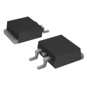
54 Uses0 StarsRGPR20NS43HRTL
IGBT 460 V 20 A 107 W Surface Mount LPDS #CommonPartsLibrary #Transistor #IGBT The RGPR20NS43HRTL specification defines the engineering requirements for an ultrafast recovery power rectifier designed for high-efficiency power conversion and switching applications. This specification establishes the functional, electrical, mechanical, thermal, environmental, and quality requirements necessary to ensure reliable rectification performance, low switching losses, and long-term operational stability in power electronic systems. The device is intended for use in switch-mode power supplies, power factor correction circuits, motor drives, industrial power equipment, and other high-frequency power conversion applications. It provides efficient current rectification with fast reverse recovery characteristics, enabling improved system efficiency and reduced electromagnetic interference in demanding electrical environments. Engineering Requirements The rectifier shall be manufactured using qualified semiconductor fabrication processes and high-quality materials to ensure consistent electrical performance, thermal stability, and long service life. The device shall maintain reliable operation under specified voltage, current, and temperature conditions without degradation of functional performance. Electrical characteristics shall provide low forward voltage drop, fast reverse recovery time, and high surge current capability to support efficient high-frequency switching applications. The device shall maintain stable electrical behavior under repetitive switching cycles and transient operating conditions. Thermal performance shall support effective heat dissipation through the package structure and recommended mounting configuration. The component shall operate within specified junction temperature limits while maintaining electrical integrity and long-term reliability under continuous or intermittent load conditions. Mechanical construction shall be suitable for standard surface-mount or through-hole assembly, depending on the package configuration, and shall withstand soldering, handling, vibration, and thermal cycling without mechanical degradation. Workmanship shall be free from defects including contamination, cracks, bond failures, corrosion, or structural inconsistencies that could adversely affect electrical or mechanical performance. Inspection, validation, and testing shall be conducted using calibrated equipment and controlled quality procedures to verify compliance with all applicable engineering and manufacturing requirements. Any deviation from this specification shall require formal engineering evaluation, documented technical justification, and approval through the established engineering change control process. Documentation Supporting documentation shall include engineering drawings, electrical performance data, thermal characterization reports, qualification records, inspection reports, and revision-controlled manufacturing documentation. All documentation shall be maintained under formal configuration management and quality assurance systems to ensure complete product traceability. Revision Control Any modification to this specification shall be managed through the formal engineering change management process. All revisions shall undergo technical review, validation, and approval before implementation to ensure continued compliance with design intent and applicable engineering standards. #EngineeringSpecification #PowerRectifier #UltrafastRecoveryDiode #PowerElectronics #SwitchModePowerSupply #IndustrialElectronics #Semiconductor #ThermalManagement #QualityAssurance #EngineeringDocumentation
0 Uses0 StarsEE-SX4081
Optical Sensor Through-Beam 0.197" (5mm) PCB Mount The EE-SX4081 specification defines the engineering requirements for a slot-type photomicrosensor designed for non-contact object detection and position sensing in electronic and electromechanical systems. This specification establishes the functional, electrical, mechanical, environmental, and quality requirements necessary to ensure accurate optical sensing, reliable switching performance, and long-term operational stability. The component is intended for use in industrial automation, office equipment, consumer electronics, and embedded control systems requiring precise detection of object presence, motion, or position. The integrated infrared emitter and phototransistor receiver provide dependable sensing through interruption of the optical path, enabling high-speed, contactless detection in compact system designs. Engineering Requirements The photomicrosensor shall be manufactured using qualified optoelectronic components and controlled production processes to ensure consistent sensing performance, mechanical integrity, and long service life. The optical assembly shall maintain accurate alignment between the emitter and receiver to provide stable detection characteristics throughout the specified operating conditions. Electrical characteristics shall provide reliable switching response, stable output behavior, and low power consumption while maintaining consistent sensitivity across the intended operating voltage and temperature ranges. The sensor shall exhibit reliable performance under normal ambient light conditions and shall maintain signal integrity during continuous operation. Mechanical construction shall ensure precise slot dimensions, secure mounting capability, and resistance to vibration, mechanical shock, and thermal cycling encountered during normal operation. The package shall be suitable for printed circuit board assembly and shall withstand standard soldering and handling processes without degradation. Workmanship shall be free from defects including contamination, optical misalignment, package damage, corrosion, or structural irregularities that could affect sensing accuracy or reliability. Inspection, validation, and testing shall be performed using calibrated equipment and controlled quality procedures to verify compliance with engineering requirements. Any deviation from this specification shall require formal engineering evaluation, documented technical justification, and approval through the established engineering change control process before implementation. Documentation Supporting documentation shall include engineering drawings, electrical specifications, optical performance data, qualification reports, inspection records, and revision-controlled manufacturing documentation. All documentation shall be maintained under formal configuration management and quality assurance systems to ensure complete traceability throughout the product lifecycle. Revision Control Any modification to this specification shall be processed through the formal engineering change management system. All revisions shall undergo technical review, validation, and approval before release to ensure continued compliance with design intent and applicable engineering standards. #EngineeringSpecification #Photomicrosensor #OpticalSensor #SlotSensor #IndustrialAutomation #EmbeddedSystems #Optoelectronics #QualityAssurance #EngineeringDocumentation #ElectronicComponents
0 Uses0 StarsSS310
DIODE SCHOTTKY 100V SMA(DO-214AC) The SS310 is a 3.0A Surface-Mount Schottky Barrier Rectifier designed for high-efficiency power conversion and protection applications. It features a low forward voltage drop and fast switching characteristics, making it suitable for DC-DC converters, switching power supplies, freewheeling diodes, polarity protection circuits, and high-frequency rectification applications. The device is commonly available in an SMC/DO-214AB surface-mount package and typically offers a maximum repetitive reverse voltage of 100V. Key Features 3.0A average forward current capability 100V maximum repetitive reverse voltage (VRRM) Schottky barrier technology for low forward voltage drop Low power loss and high efficiency High surge current capability Fast switching speed Suitable for high-frequency applications Surface-mount package for automated assembly High-temperature soldering capability (260°C / 10 s) RoHS compliant and halogen-free variants available from some manufacturers Typical Applications Switching power supplies (SMPS) DC-DC converters Battery-powered devices Reverse polarity protection Freewheeling and flyback circuits Power management systems High-frequency rectification #SS310 #SchottkyDiode #Rectifier #PowerElectronics #SMPS #DCDCConverter #LowForwardVoltage #SurfaceMount #HighEfficiency #CircuitProtection #ElectronicsDesign #PCBDesign
94 Uses0 StarsTPS274160BRLHR
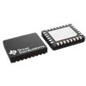
Power Switch/Driver 1:1 N-Channel 1.35A 28-WQFN (4x5) The TPS274160 device is a smart high-side switch with four integrated 160-mΩ NMOS power FETs and a chargepump to drive the gates. The device offers robust protection and diagnostic features to drive various loads (inductive, capacitive, and resistive) such as low wattage bulbs, LEDs, relays, solenoids, heaters, and sub-modules. The part enables flexible, multi-channel output configurations through paralleling channels and is in a very small WQFN package to enable usage in space constrained applications. The device is protected against short circuit events and over-temperature events, safely shutting off the output during fault events. The device also implements an external adjustable current limiting feature. This feature improves the reliability of the system by reducing inrush current when driving large capacitive loads and minimizing overload current thereby eliminating system supply brown out condition. The device also integrates diagnostic features like output current monitoring (version B) and open load detection to enable improved intelligence in modules and to enable predictive maintenance functionality. • Quad-channel 160-mΩ smart high-side switch • Wide DC operating voltage range: 5 V to 36 V – 50-V absolute maximum voltage • Accurate adjustable current limiting (250 mA to 4 A) • Intelligent diagnostic features – TPS274160A: Open-drain fault output – TPS274160B: Analog current sense – Open-load or short to supply detection in the off-state • Robust protection features – Short-circuit protection – Inductive load flyback clamp – Undervoltage lockout (UVLO) protection – Loss of GND protection • Excellent ESD protection on VS and OUT pins – ±8/±15 kV IEC 61000-4-2 ESD contact/air discharge • Available in small and 28-pin leadless QFN packages • Functional Safety-Capable – Documentation available to aid functional safety system design 2 Applications • Digital output modules • Standalone remote I/O • Motor drives • Solenoid or valve drive #TexasInstruments #TPS274160BRLHR #HighSideSwitch #SmartSwitch #IndustrialAutomation #PowerManagement #LoadDriver #CurrentLimiting #ProtectionIC #IndustrialControl #RemoteIO #SolenoidDriver #MotorDrive #EmbeddedSystems #ElectronicsDesign
45 Uses0 StarsBT151-600R
The BT151-600R specification defines the engineering requirements for a high-power silicon controlled rectifier designed for phase control and switching applications in electronic power systems. This specification establishes the functional, electrical, mechanical, environmental, and quality requirements necessary to ensure reliable switching performance, controlled power regulation, and long-term operational stability. The device is intended for use in applications requiring efficient control of AC power or high-current DC switching, such as motor speed control, light dimming, power regulation circuits, and industrial control systems. It provides controlled conduction behavior triggered by gate activation and remains in conduction until current falls below the holding condition. Engineering Requirements The semiconductor device shall be manufactured using controlled silicon processing techniques to ensure stable thyristor operation, consistent triggering characteristics, and reliable current handling capability. The device shall maintain predictable switching behavior under defined electrical, thermal, and environmental operating conditions. Electrical characteristics shall ensure reliable gate triggering sensitivity, stable on-state conduction, and controlled turn-off behavior under appropriate circuit conditions. The device shall maintain performance integrity under surge conditions and repetitive switching operation within its design limits. Thermal performance shall support efficient heat dissipation through the package structure and mounting interface. The device shall be suitable for attachment to appropriate heat sinking systems to maintain safe operating junction conditions during continuous or high-load operation. Mechanical and package construction shall be suitable for surface-mount or power PCB assembly and shall ensure robust mechanical stability during soldering, handling, and thermal cycling. Workmanship shall be free from defects such as contamination, cracks, bond wire issues, or structural inconsistencies that could impact performance or reliability. Inspection, validation, and testing shall be performed using controlled procedures and calibrated equipment to ensure compliance with all applicable engineering and quality requirements. Any deviation from this specification shall require formal engineering review, documented justification, and approval through established change control processes. Documentation Supporting documentation shall include official datasheets, electrical characterization reports, thermal performance data, qualification test records, inspection reports, and revision-controlled manufacturing documentation. All documentation shall be maintained under formal configuration management and quality assurance systems to ensure traceability and consistency. Revision Control Any modification to this specification shall be managed through formal engineering change control procedures. All revisions shall undergo technical review, validation, and approval prior to implementation to ensure continued compliance with design intent and applicable standards. #EngineeringSpecification #SCR #Thyristor #PowerElectronics #PhaseControl #IndustrialControl #Semiconductor #PowerSwitching #QualityAssurance #EngineeringDocumentation
1 Uses0 Stars